Announcement

Collapse
No announcement yet.

Nelsonmxmarc 1993 GTSt Type-M Build / Tips-tricks for HCR32 (Skyleezy!)

Collapse
X
 
  • Filter
  • Time
  • Show
Clear All
new posts

  • Awesome! Thanks Mark!

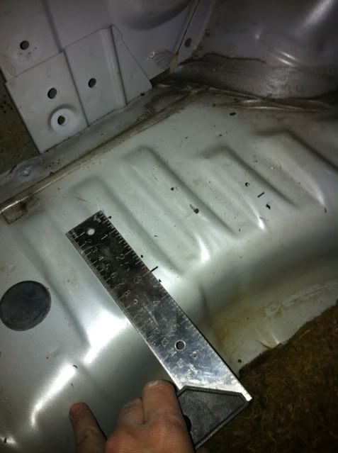
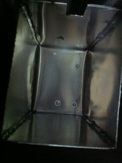
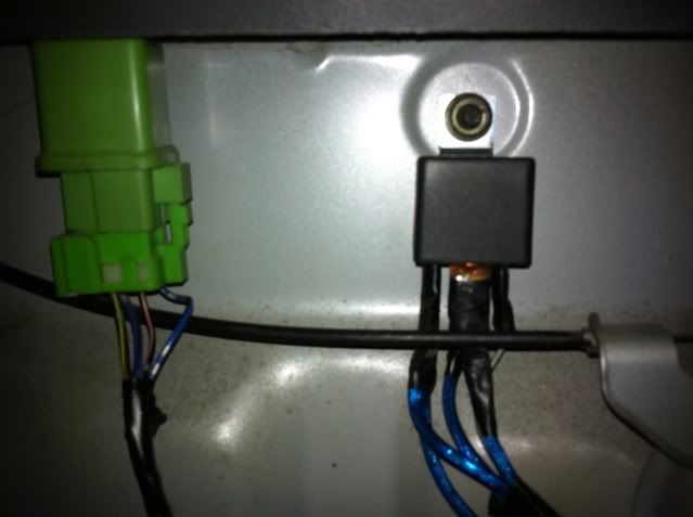
    As for the holes, I drilled 3 small holes in the box; using the ridges on that side of the trunk, there was enough material with the raised portions to fit decent sized screws. Drill a small pilot hole and you'll see, it'll be fine. Use a self tapping or metal screw with a pilot hole and you should be good! I'll get you some pics shortly
    Check out the GTST Projects page and keep up to date with my build!
    www.nelsonmx.wordpress.com
    Like us on Facebook! www.facebook.com/NelsonMX
    Any part inquiries can be forwarded to marc@nelsonmx.com

    Comment


    • Alright;

      Holes are drilled at 1" from the hump on both, and the final at the bottom, 3 inches from.

      Follow the flat line parallel to the hump - the dots in this range is where i made my pilot holes.

      I used small screws, about half inch metal screws. I had enough meat to get through the carpet and the washers i mounted as well.

      It's SOLID


      Last edited by nelsonmxmarc; 02-22-2011, 11:18 AM.
      Check out the GTST Projects page and keep up to date with my build!
      www.nelsonmx.wordpress.com
      Like us on Facebook! www.facebook.com/NelsonMX
      Any part inquiries can be forwarded to marc@nelsonmx.com

      Comment


      • ^^ you just have to be carefull not to drill into the frame rails
        sigpic

        [links to all chapters in first post]

        Comment


        • So Marc if you cut the box in the trunk out and direct feed that wire to the 12v source that should be an improvement? I have no problem doing this because my battery must go to the trunk.
          Miss driving sooooo bad! Need to get a car on the road ASAP!

          Comment


          • Originally posted by frankiman View Post
            ^^ you just have to be carefull not to drill into the frame rails
            Exactly, or any other goodies below, and why i opted for shallower screws. There's plenty of grab with half inch, and compensating for carpet thickness (with no padding underneath) and washers, you're only into the meat of the metal by maybe a quarter inch, which lays you flush with the bottom of the hump. Clearance to the rails (which are quite far away) and heat shield is quite a bit.

            Chris,
            depends what you mean by improvement. Most stock wiring tends to degrade over time. If you look at the general voltage at pump readout it's usually in the 11.4 v range. You can enhance the feed to the pump by a volt or 2 depending on the batteries output. And by ground your earth wire (white) the returning signal to the ECU will always readout that given voltage. The white wire acts as a kind of homeostatic agent, returning the feed to a baseline of <12 volts. The system is a bit more complex, but SAU has a good write up about it that's quite interesting!

            I'll eventually put in a direct feed and do a proper write up here
            Check out the GTST Projects page and keep up to date with my build!
            www.nelsonmx.wordpress.com
            Like us on Facebook! www.facebook.com/NelsonMX
            Any part inquiries can be forwarded to marc@nelsonmx.com

            Comment


            • I just have boost a pump by kenne bell that will just juice my pump up to 17V.

              NBD. More proper this way IMO.

              Comment


              • Worth picking up? Have you tried between the direct 12v feed and the Kenne bell setup?
                Check out the GTST Projects page and keep up to date with my build!
                www.nelsonmx.wordpress.com
                Like us on Facebook! www.facebook.com/NelsonMX
                Any part inquiries can be forwarded to marc@nelsonmx.com

                Comment


                • It switches in similar way as factory when revs rise and is adjustable from inside cabin -

                  404 Page not found Here are some useful links: Home Page Superchargers Parts Support/Contact


                  Test's to show it works -

                  404 Page not found Here are some useful links: Home Page Superchargers Parts Support/Contact


                  Makes a 238lph fuelpump become a 378lph fuelpump.

                  With running full voltage to fuelpump all the time you can put unnecessary stress on alternator when light's, etc are on at idle?, heat the fuel up (would need to install fuel cooler), brush type fuelpump fails earlier. You can buy brushless high performance fuelpumps that are rebuildable.
                  Last edited by Skym; 02-22-2011, 09:29 PM.
                  RESPONSE MONSTER

                  The most epic signature ever "epic".

                  Comment


                  • Originally posted by Skym View Post
                    It switches in similar way as factory when revs rise and is adjustable from inside cabin -

                    404 Page not found Here are some useful links: Home Page Superchargers Parts Support/Contact


                    Test's to show it works -

                    404 Page not found Here are some useful links: Home Page Superchargers Parts Support/Contact


                    Makes a 238lph fuelpump become a 378lph fuelpump.

                    With running full voltage to fuelpump all the time you can put unnecessary stress on alternator when light's, etc are on at idle?, heat the fuel up (would need to install fuel cooler), brush type fuelpump fails earlier. You can buy brushless high performance fuelpumps that are rebuildable.

                    Yeah I have that controller too.

                    The fuel pump set up I have will be running off its own relay from the battery then connected to Kenne Bell for extra juice when I need it.

                    Comment


                    • Hmm cool! Usually you hear or see something like this and automatically assume 'gimmick' but that's interesting! I'll be sorting out a 12v source and relay tomorrow night, so maybe i'll go this route in the future. Mind you, i'm running a GTR pump atm; eventually i'll need to uprate to something more lively and "new".
                      Check out the GTST Projects page and keep up to date with my build!
                      www.nelsonmx.wordpress.com
                      Like us on Facebook! www.facebook.com/NelsonMX
                      Any part inquiries can be forwarded to marc@nelsonmx.com

                      Comment


                      • Ok so a little update.. ARP bolts are here! And the head is in the process of going back on..

                        I just need to torque the headstuds with a deep 1/2" 12 point, which for some reason i can't seem to find at work.

                        Also pulled the lifters to polish the mating surface so the new cams have a perfectly smooth contact surface.

                        AND, i installed a relay for my fuel pump, here's a little how to;


                        If your battery is in the trunk, you're more than safe running 10awg-16awg. Because it's a short distance, you can effectively move the 14 or so amps max. that your wiring loom will see without an issue.

                        Also, a 30 amp fuse is not necessary. The most people have seen in this setup is 14 amps, so a 20a fuse will suffice.

                        I'm going to explain this in laments terms, only because every thread i read about this has some 'electrician' standpoint which is just a bunch of jargon the normal DIY person doesn't really grasp.

                        1. You need to source a relay. The relay needs to be capable of transferring 12VDC (NOT AC) and a rating greater than that of the inline fuse you'll be using - in this case 30a + will be fine.

                        2. Once you have a your relay, find yourself an inline-spade-type fuse holder like what you see here (Black thing, red wire)


                        Since our battery is in the trunk, and we know that 10-16 awg is safe, get hold of a fuse holder of the same size. I went with 14 awg all around.

                        Now the fun part, reading the relay.

                        Most relays have the same readouts as that posted in the photo above, which makes this quite simple.

                        Basically, looking at the relay top, you'll see this;
                        (high amperage rating)


                        #30 is your POWER in from the battery. Between your battery and the relay is your FUSE
                        #85 is your SIGNAL wire, which tells the relay to close (Creating a circuit/switch, grade 11 physics!). This is done by introducing power, which in this case is 12v signal on from the ECU or ANY wire than provides 12v on ignition. (ECU is safest for fuel cut in the event of an accident)
                        #86 is your GROUND. There are TWO - one on the fuel pump, and one to the chassis. This means you need to T off 2 wires from this connection.
                        #87 is your POWER to FUEL PUMP

                        1. First things first, wire all the wires accordingly to their posts on the relay. These are all fresh and have nothing to do with the car at this point, so make sure everything is all set up, like so;


                        2. Next, locate and remove your fuel pump. Once it's out, locate the POWER and GROUND terminals. The colour of these wires for an R32 fuel pump harness is

                        POWER --> White with purple stripe
                        GROUND --> Blue with red stripe

                        Cut these, and solder your new power and ground from your relay (87 and 86)


                        3. Reinstall the pump

                        4. Finding your signal wire..
                        At the rear of the trunk with the lining off is a small green relay, this relay is the corresponding relay for the OEM fuel pump harness and voltage regulating system.

                        The ONLY 12v source at ignition that i could retrieve was the BLACK with PINK STRIPE and SILVER SPOTTED wire;


                        You can see it under the green harness, second from the right.

                        This provides 12v to signal the relay. You dont need 12v, of course, since the relay would operate normally at anything around 4, but since this provides 12v, we know that it's a direct feed from the ignition harness and is what we're after.

                        Cut this wire from the existing relay, and solder your relay SIGNAL wire to LIVE end (dont solder this to the connector to the relay! lol)
                        This gets rid of #85

                        5. Mount your relay; i used the bumper bolt on the rear of the trunk next to the existing relay. There is a ground just to the left of it for the rear lights, this is fine to use.

                        6. Ground the relay to the chassis (remember, fuel pump is already ground but its not ground to earth yet)

                        7. Take your power to relay wire and mount it on the + terminal of the battery - this gets rid of #30.

                        8. Place your fuse in the fuse holder

                        9. Test it out!

                        ACC will not activate the pump, placing it in ignition, like you normally would, will now activate the pump to prime. You will find it's substantially louder as the pump is no longer regulated, and is running at a constant 13.8v or wtv output your battery is capable of.


                        Done.


                        In theory, yes, you are moving more fuel to the engine bay, thus heating fuel up and returning it to the tank. HOWEVER, this will get rid of some hesitation issues on and off throttle as the voltage regulator kicks in everytime the supply of fuel is cut (foot off) - so between shifts, and etc.

                        There has a been a lot of praise to this method on SAU and i can't see the negatives besides killing the pump (stock) due to constant power, as well as hotter fuel entering the tank. However, if you run a brushless or uprated pump other than stock, your system will be more than adequate to handle the extra power. Also, most people complain that voltage drop due to old wiring harnesses and such has shown max voltage to be in some cases, 11.4v, which is quite low.
                        Last edited by nelsonmxmarc; 02-25-2011, 08:05 PM.
                        Check out the GTST Projects page and keep up to date with my build!
                        www.nelsonmx.wordpress.com
                        Like us on Facebook! www.facebook.com/NelsonMX
                        Any part inquiries can be forwarded to marc@nelsonmx.com

                        Comment


                        • holy progress marc! great work man,

                          why do you need everything done by march 15?
                          The SkyLife Community & News Website --> http://www.skylife4ever.com

                          Comment


                          • I wish I would have everything done by march 13th! Not going to happen.

                            Oh I know why he needs to be done by the 13th, to be able to drive up and help me finish my car.... Lol
                            Miss driving sooooo bad! Need to get a car on the road ASAP!

                            Comment


                            • This is great Marc! Serously going to try and tackle this within the next week or 2. Great info man as usual.
                              Traction is optional, so are zipties

                              92 Gtst/Silver bullet

                              Comment


                              • Haha thanks Tanner, let me know if you need any pointers as it's a bit confusing at first, but i'm sure you'll figure it out.

                                Yea progress is goooood.. March 15th because the tire law is lifted and i can drive the car on the street. I need it out and running to make sure theres no leaks and it's 100%, then i'm tossing the idea around of going to toronto to have my car tuned since ill be there for my birthday (fml), for my cousins wedding. So i planned to drive the car down.. I can tune the z32 maf in, and probably toss some timing in and enrichment values for the turbo, but i just want it done properly. I spoke to Haig, Robin's going to be back mid April. I'm just not sure how long i want to wait and even if it's worth waiting on Robin in case he bails.

                                Anyways, the roads are Sh*t and the car wont be driving anywhere in March unless by some divine miracle, they fix them, all.

                                I'm going to get a 12 point 1/2 inch deep deep today and sort out the head / cams. Waiting on Haig for a few parts, like a new rear main which i may or may not have mangled on install .. LOL fml..
                                Check out the GTST Projects page and keep up to date with my build!
                                www.nelsonmx.wordpress.com
                                Like us on Facebook! www.facebook.com/NelsonMX
                                Any part inquiries can be forwarded to marc@nelsonmx.com

                                Comment

                                Working...
                                X