Originally posted by PurpleStreak
View Post
Announcement
Collapse
No announcement yet.
Work Log: R33 GT-R
Collapse
X
-
Shoulda got someone that's been there to helpOriginally posted by PurpleStreak View PostIt pissed me off to no end, but hopefully my solution fits up nicely; then I can share it with you guys! I'm on my what, 3rd engine? plus I've pulled/installed 3 others haha. No, my engine failures were not install/removal issues haha.
Black 1991 GTR. Serious garage stand mantle/parts car.
Black 1990 Pulsar GTiR. Sold
Silver 1989 GTR. Sold
Black 2010 Subaru WRX. Weekend warrior. Sold.
Black 2013 F-150 FX4 ecoboost. Daily driver.
White 2012 Ford Explorer Limited. Family wagon.
Sorry for my offensive comments, I r socially retard.
lolstart by having A ROLLING GTR then we talk u ******* mofo funzy little *****
Comment
-
No doubt; but I do get satisfaction from doing it myself. I'll let you know when I get to an engine pulling stageOriginally posted by NismoS-tune View PostShoulda got someone that's been there to help I'm on my what, 3rd engine? plus I've pulled/installed 3 others haha. No, my engine failures were not install/removal issues haha.
 (which hopefully won't be for a while)
Onward with the turbo swap...
Firstly I changed all the studs on the -5s as I felt they were too short. It did have sufficient bolt engagement but why take a chance?
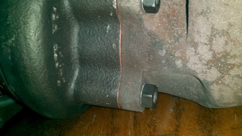
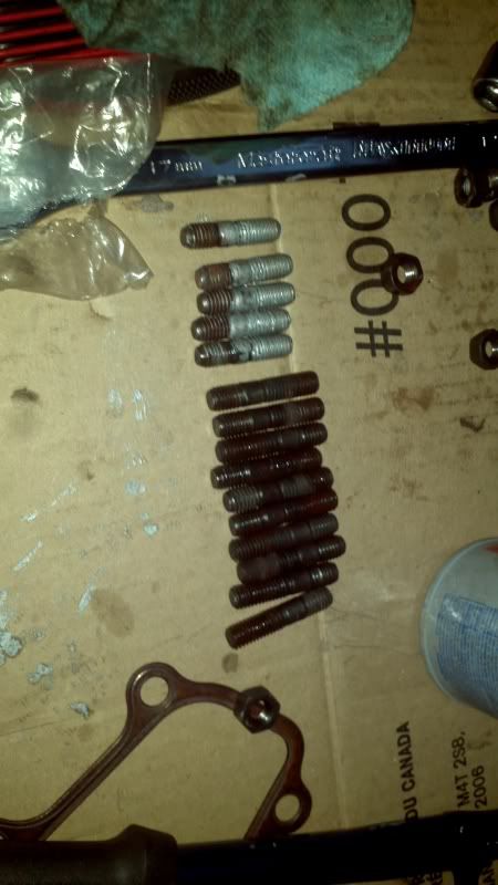
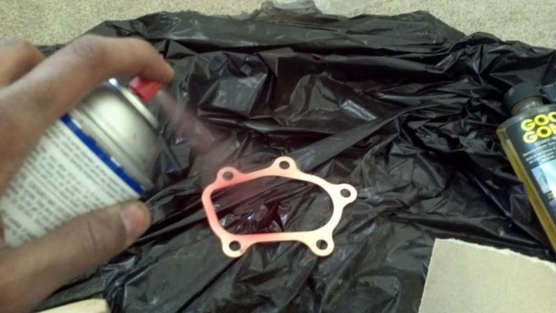
With the studs changed, the turbo dump pipes can be installed. A healthy dose of Permatex gasket sealant is required for the copper gasket. I guess I should be using the copper sealant spray (phenolic) but the high tack spray (vinyl acetate) has the same temperature range as the copper spray ( up to 500 F). Liberal application of anti-seize paste is also required.
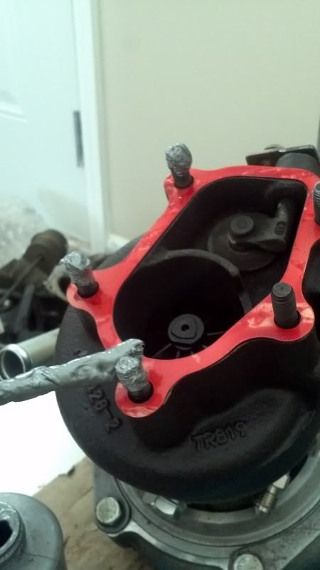
All the fittings and respective braided lines can then be installed. I got Thermo Tec heat shield sleeves for the braided lines (rated to protect up to 750 F conductive, 2000 F radiant) as I am paranoid about melted lines due to the proximity to the turbines.

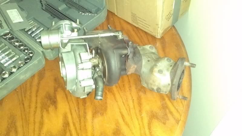
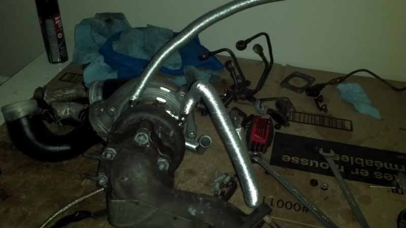
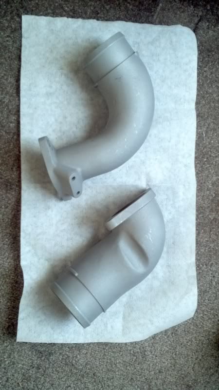
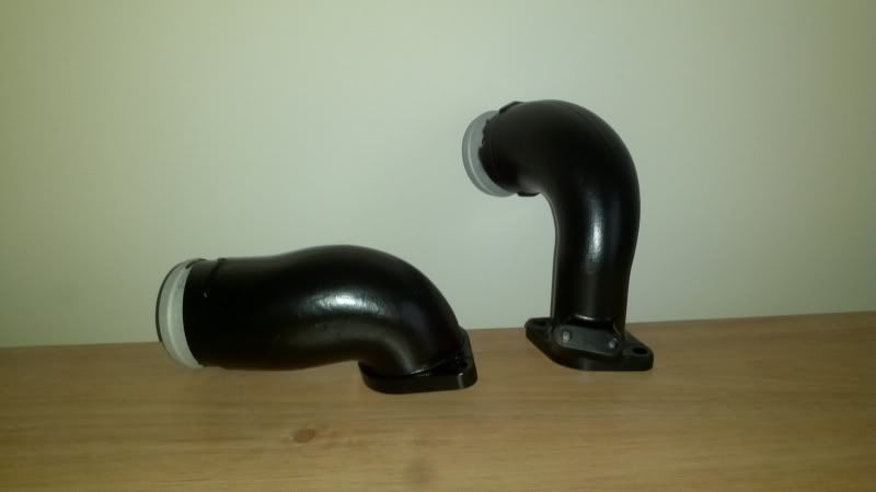
The Greddy kit does not replace the inlet and outlet piping on the rear turbo. So i sand blasted and painted them flat black with caliper paint.
I also purchased some universal titania sensors and M18xM12 bung adapters to install, as Nistune requires titania sensors as found in the R32 GTR.
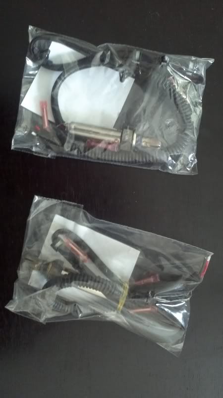
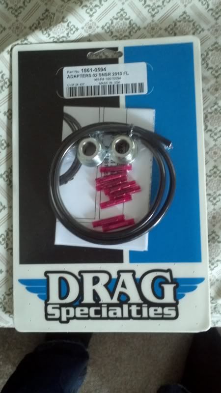
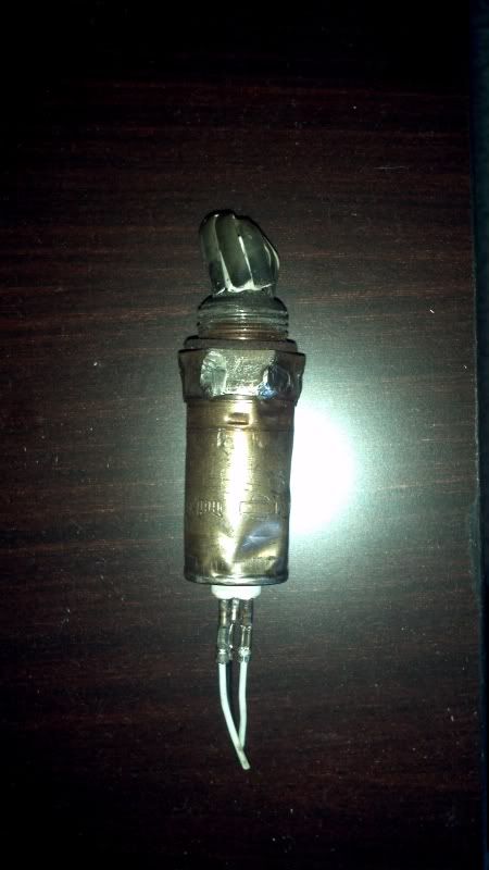
Unfortunately, the factory bung that threads in to the dump pipe came out with the R33 O2 sensor; what a mission it was to get it off! I had to recruit one of my tougher buddies to muscle it off in the end.
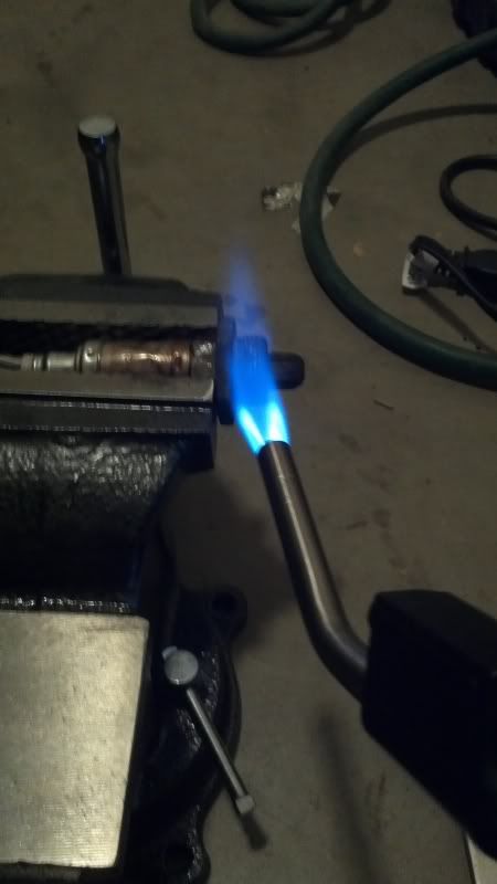
Afterwards, I beat the crap out of it to show it who's BOSS
I didnt want to solder the wires to the R33 connectors (allegedly there is some stainless steel wiring, and I am not the most skilled solderer); so I used butt connectors.
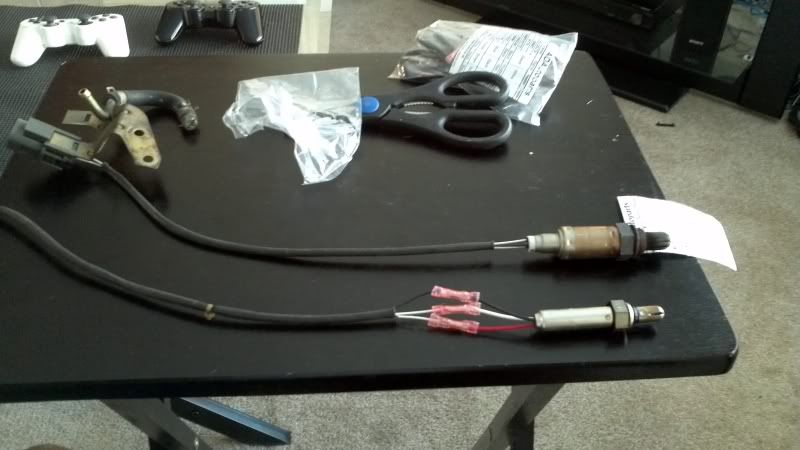
I then installed the O2 sensors (with anti-seize of course) and the rear compressor inlet/outlet piping.
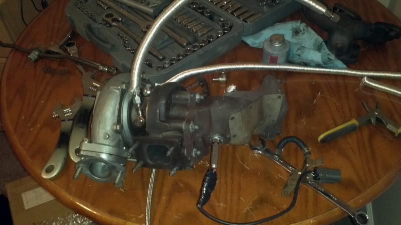
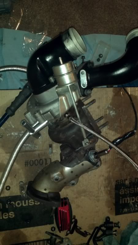
With this the turbo assemblies are ready to be installed!Last edited by PurpleStreak; 04-12-2012, 12:50 PM.
Comment
-
Nice work! Should be a beast around 500whp!! I won't be able to keep up in the the pulsar or GTR but R33s are meant to be faster
Where are you getting tuned? What do you have for a base tune to get there?Black 1991 GTR. Serious garage stand mantle/parts car.
Black 1990 Pulsar GTiR. Sold
Silver 1989 GTR. Sold
Black 2010 Subaru WRX. Weekend warrior. Sold.
Black 2013 F-150 FX4 ecoboost. Daily driver.
White 2012 Ford Explorer Limited. Family wagon.
Sorry for my offensive comments, I r socially retard.
lolstart by having A ROLLING GTR then we talk u ******* mofo funzy little *****
Comment
-
Very nice , you'll take the intake pipes back off for the install though or you wont get to all the nuts
Also dont put any sealer on the dump pipe gaskets , you dont need to with the stainless ones and the temp of the dumppipe will easily exceed the temp range fo that gasket sealer , expect temps in excess of 1200 degrees there under full boost ..
Comment
-
Originally posted by NismoS-tune View PostNice work! Should be a beast around 500whp!! I won't be able to keep up in the the pulsar or GTR but R33s are meant to be faster
Where are you getting tuned? What do you have for a base tune to get there?
Haha I see you are coming around to the whale after all
I'm probably going to go with Autodream in Calgary; they installed Nistune in the R32 ECU for me, along with groundign the pin for heating the O2 sensor. They only have a RWD dyno but I'll get them to take out the front driveshaft. Its much easier for me to go a shop in Calgary instead of Red Deer anyways..
As for base tune, is there such a thing as base maps you can get for Nistune? Have'nt come across user maps for bigger turbos yet..I was going to call this Lightspeed guy who is supposedly in Fort Mac to do a street tune. Do you know of anyone else up here?
Comment
-
Which nuts are you referring to? I already have the rear turbo installed, just haven't updated yetOriginally posted by cortexx View PostVery nice , you'll take the intake pipes back off for the install though or you wont get to all the nuts
Also dont put any sealer on the dump pipe gaskets , you dont need to with the stainless ones and the temp of the dumppipe will easily exceed the temp range fo that gasket sealer , expect temps in excess of 1200 degrees there under full boost .. Im reinstalling in the order of removal.
And your absolutely right about the sealer, Permatex mentions exhaust manifold gaskets as an application, but still lists max temp as 500 F??
EDIT: It appears both sealants have similar ingridients and propellant, with the hi-temp sealant adding a minute concentration of copper to promote heat transfer and dissipate heat. I called Permatex, they say either sealant will embrittle past 500 F, but will stay in place till removed. In retrospect, I shouldnt have sprayed them!Last edited by PurpleStreak; 04-12-2012, 03:35 PM.
Comment
-
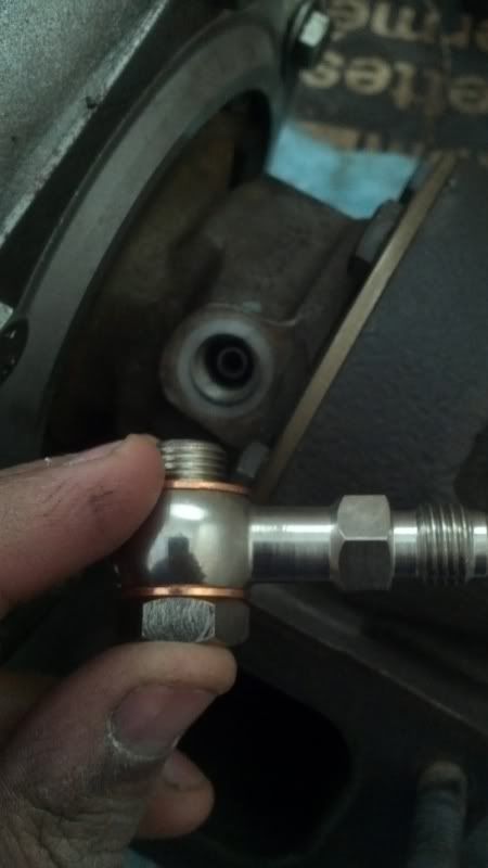
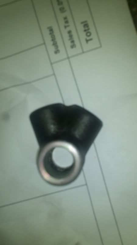
The stock coolant and oil fittings also need to have adapters installed to fit the -AN hose. The coolant return fitting needed some minor work. The female ends are for flare fittings; thus simply threading the adapter in is not enough to seal. Copper washers must be installed for keeping the fluid in(Thanks for your help on this Paul). Since this is a cast fitting, the surface where the washers would sit wasnt flat at all. I did some minor grinding with a Dremel (which looks quite terrible), and then used RTV gasket maker along with the copper washer to fill out any pockets.
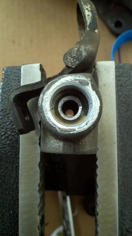
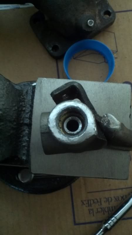
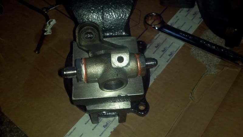
The coolant supply fitting has a much nicer finish on the female ends, and is suitable for sealing with washers.
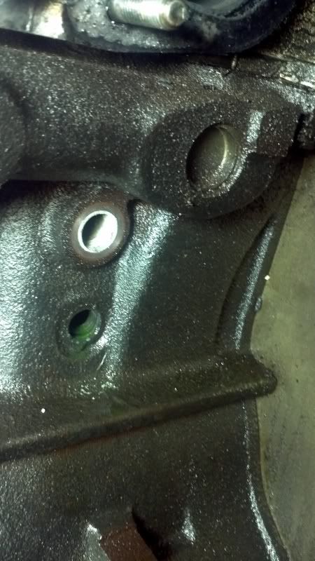
The entire oil supply fitting is replaced by a metric thread to -AN adapter, and -AN tee.
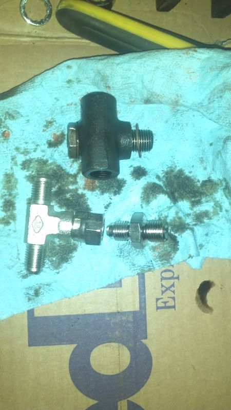
I installed these fittings on the block and commenced with installation of the turbo. The rear turbo assembly had to be installed with its manifold. With this method, the braided lines have to be installed to the turbo assembly first, then the manifold gets bolted on to the turbo assembly. This is done as there is no access to the coolant and oil fittings on the turbo bearing housing otherwise. The turbo is then lowered into the engine bay so that the coolant line can be fastened to the block fitting.
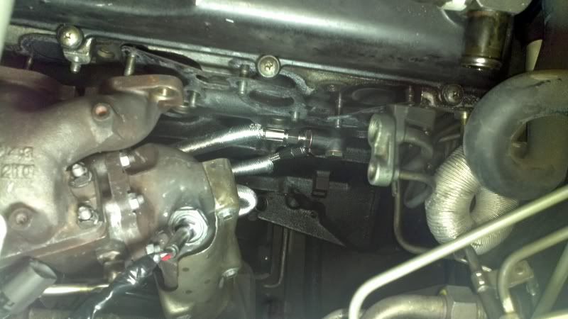
And then, the entire assembly can be placed on the manifold studs and fastened in a couple of locations. This is best done while squatting on top of the engine.
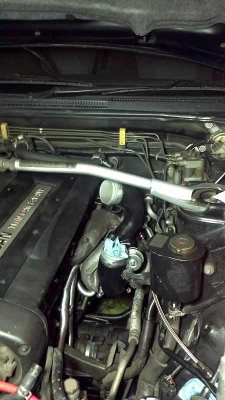
I then went underneath to check out the auxiliaries; only to find this rat's nest.
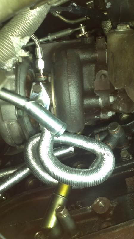
Congested much? I'm sure the bends are way smaller than the minimum bend radius on these things. Anyway I messed around with it so that there werent any major kinks and so that the sleeves weren't touching the turbine. I may yet install a couple of elbows to remove the tight bends and get a cleaner routing going.
After this was done, the painful process of torquing the rear manifold began. This was made more difficult with the extra braided lines between the turbo assembly and block, but I was done torquing in a solid three hours
Next up will be cleaning up the auxiliary lines to avoid major bends and installing the oil drain hose. Then, installing the front can begin (which appears much easier now in terms of line routing)
Comment
-
When you want to use AN fittings in place of Flared fittings, the adapters can be bought that are O ring sealed and require no modding (the copper fittings look nice! what thread size was that?)
For dyno tuning on the RWD, just pull the 4wd fuse or if you have a TSC, even better, either will disable the transfercase. No need to do all the work of pulling the front driveshaft.Black 1991 GTR. Serious garage stand mantle/parts car.
Black 1990 Pulsar GTiR. Sold
Silver 1989 GTR. Sold
Black 2010 Subaru WRX. Weekend warrior. Sold.
Black 2013 F-150 FX4 ecoboost. Daily driver.
White 2012 Ford Explorer Limited. Family wagon.
Sorry for my offensive comments, I r socially retard.
lolstart by having A ROLLING GTR then we talk u ******* mofo funzy little *****
Comment
-
Frank, I just found those, metric concave seat to -AN adapters, wish I'd known about them sooner! I was looking for them because at first it was looking promising, all the lines were routing nicely, but then, the oil feed adapter and -4AN tee fouls big time against the dump pipe in its final position. I picked up two for the oil feed and two for the water feed in case it leaks (from Pegasus Auto Racing Supplies)Originally posted by NismoS-tune View PostWhen you want to use AN fittings in place of Flared fittings, the adapters can be bought that are O ring sealed and require no modding (the copper fittings look nice! what thread size was that?)
For dyno tuning on the RWD, just pull the 4wd fuse or if you have a TSC, even better, either will disable the transfercase. No need to do all the work of pulling the front driveshaft.
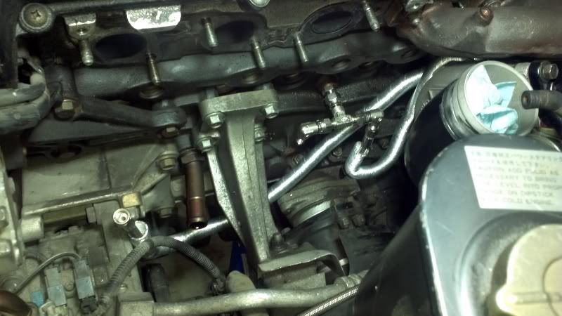
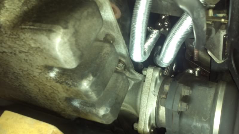
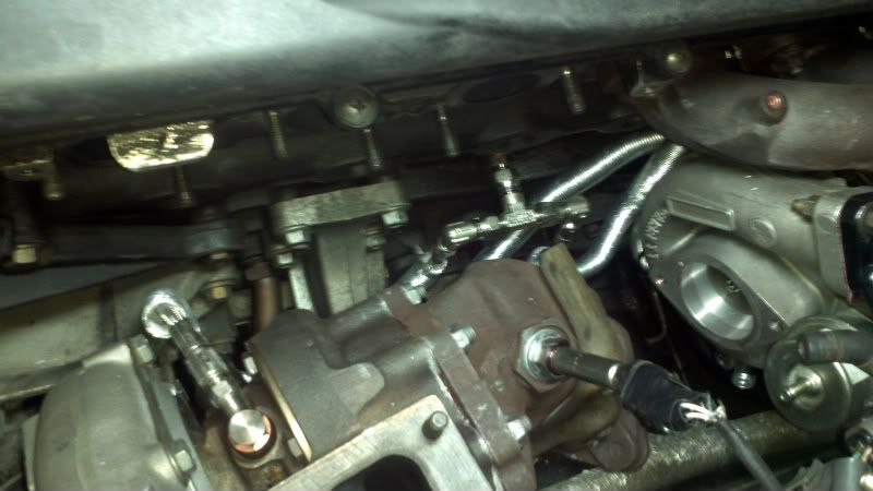
The adapter sizes are
Oil Feed Banjo bolt and metric seated fittings - M12 x 1.0
Water Feed Banjo bolt and metric seated fittings - M14 x 1.5
Water Return seated fittings - I can check this but I didn't bother to at the time - I drilled down the seat so the adapter would fully seat the washer! But at least its much more easily accessed, and it doesn't bother me at all if it doesnt leak..
And Paul was right about the intake pipes lol Last edited by PurpleStreak; 04-15-2012, 01:56 PM.
Comment
-
Ok, so I got most of the work done, but before I update the remainder of the turbo related work, I should clean up any update surrounding the secondary work that needed to be done.
While I was waiting for the oil feed fittings (which I screwed up the first time by ordering convex seat instead of concave), I installed the water temp gauge fitting and Nismo oil separator. I finished the remainder of the separator installation once I had my intake piping bolted up, which is why you’ll see the piping in the some of the separator pictures.
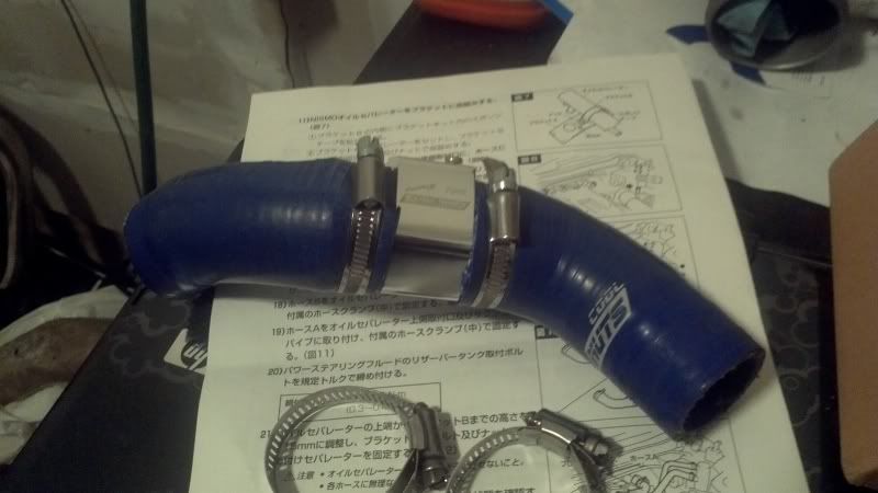
For the water temp fitting, I followed Cortexx’s build by purchasing a radiator hose water temp gauge adapter. I noted that the 38mm adapter he bought was a bit of a tight squeeze. I measured my ‘Cool Nuts’ hose from the previous owner and it was around 29-30mm ID. So I picked up a $10 eBay 34mm adapter for just a bit of snugness.
I was very happy to see that when it arrived, it was also made by ‘Cool Nuts’! Clearly me and the previous owner share some affinity for CDM parts! I installed it on the hose, installed the water temperature sensor and installed the hose back on the car. I put some loom on the wire to make it look neater after.
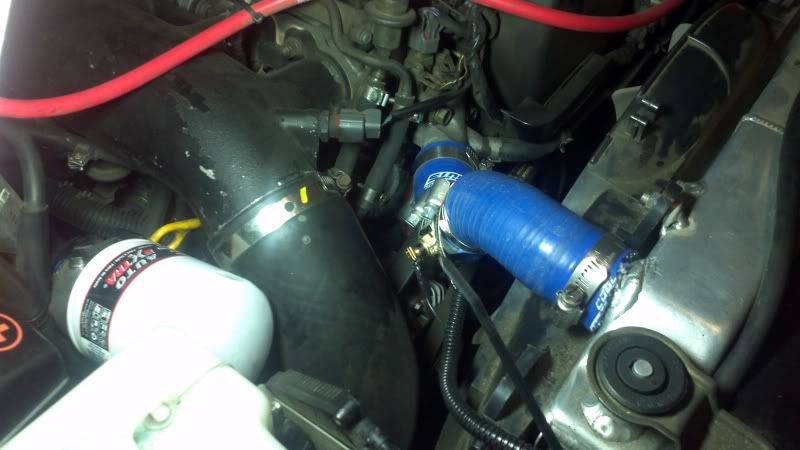
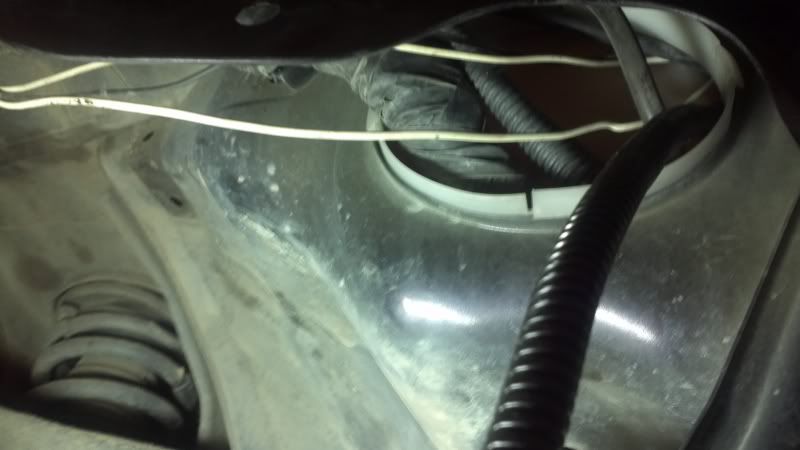
I ran the wiring through the driver’s side grommet as usual.
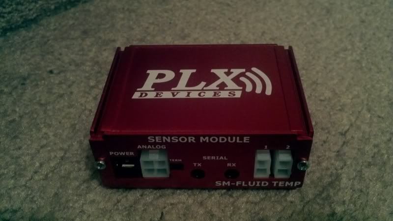
The gauge I will be using is a PLX multi gauge. It doesn’t look very sophisticated, but I like the idea of using one gauge for different readouts. This is done by purchasing different sensor modules and connecting them in a daisy chain.
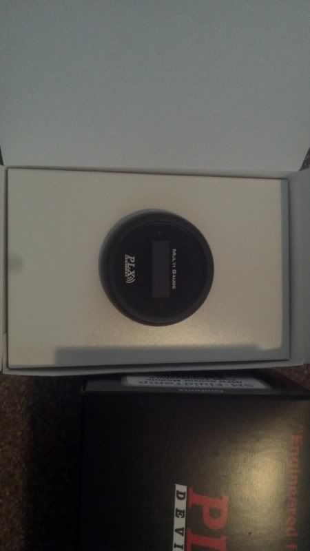
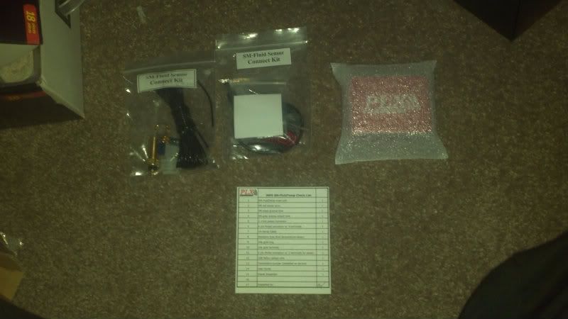
Here is the sensor module itself, and the kit, for fluid temperature. The sensor is made by VDO.
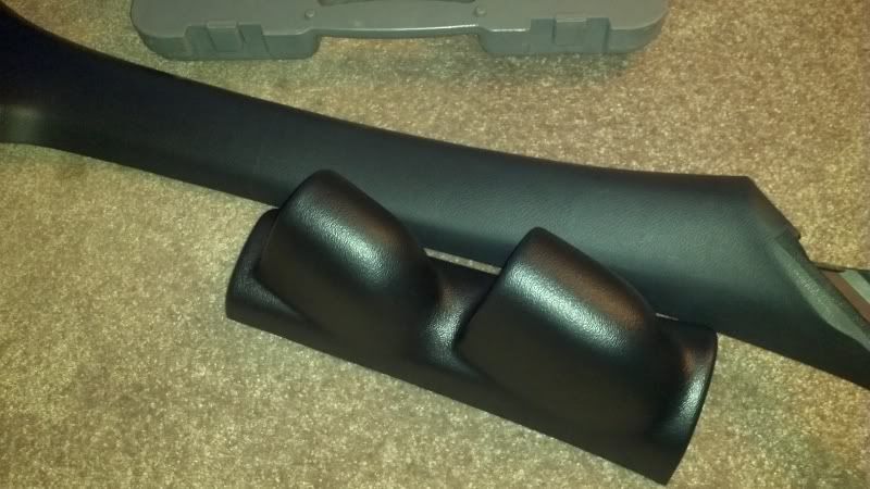
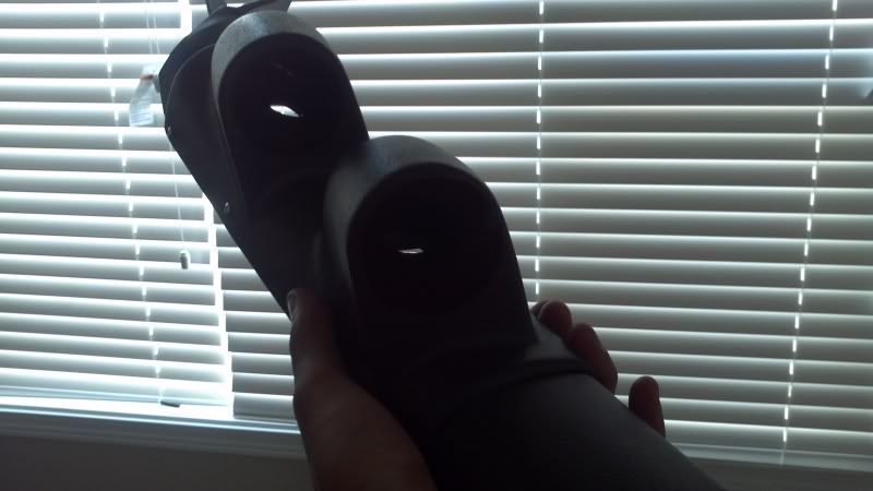
For the gauge pod, I picked up a Gaugeworks 2” Pod for R33 made by Autometer. Who knew Autometer had even heard of the Skyline! It is a nice fit but my gauges are 2 1/16”, so some filing will be required. I marked where I wanted the pod to go on the pillar before I peeled off the pillar to start.
Due to time constraints, I elected to go with some rivets. Some 1/8” steel rivets with ½” grip range, with backing plates on the inside of the pillar, ensures that the pod will not go anywhere. I will have to clean up the aesthetics later. I drilled a few holes for the pod, lined up and drilled a couple of holes through the pillar, secured it with a couple of rivets, and drilled the remaining holes and installed the remaining rivets.
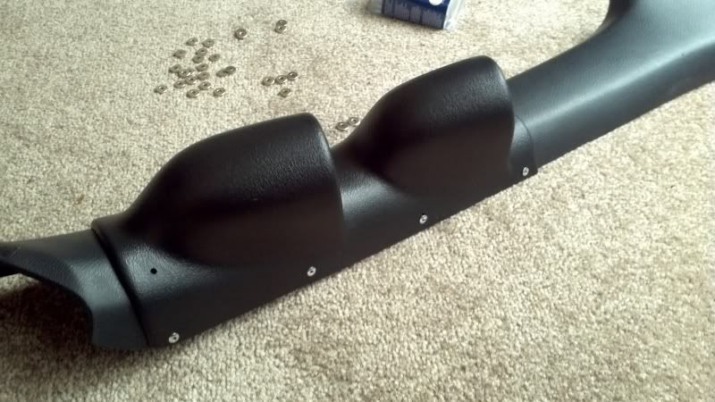
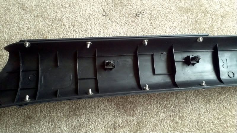
I then drilled a hole for the wiring for each gauge. I later enlarged the hole for ease of access.
Comment
-
Onto the Nismo Oil Separator.
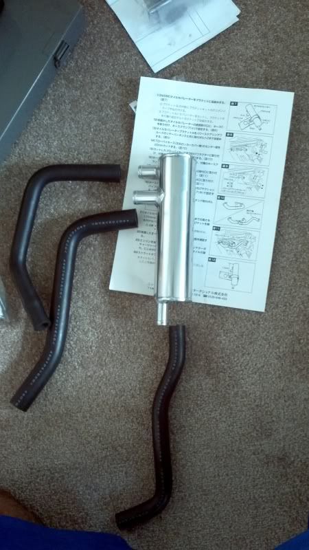
This was by far the easiest, most enjoyable installation I had done on the car! Everything fits perfectly. I spent a bit of time deciphering the Japanese instructions, but pictures sure make it easy!
This is basically the final layout of the hoses hooking up to the separator.
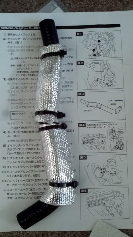
First, the instructions say to wrap the oil drain line in heat shielding.
Next it says to position the separator a distance of (120mm?) from the top of the can to the top of the C-clamp.
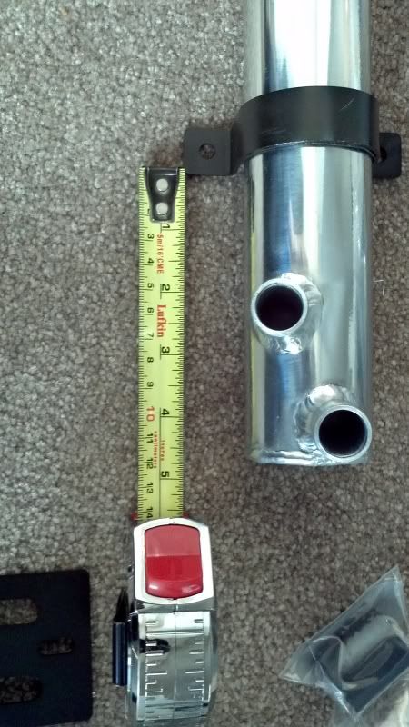
Next the can may be fixed to the bracket using the C-clamp. It comes with a little strip of rubber to go on the inside of the clamp to protect the can.
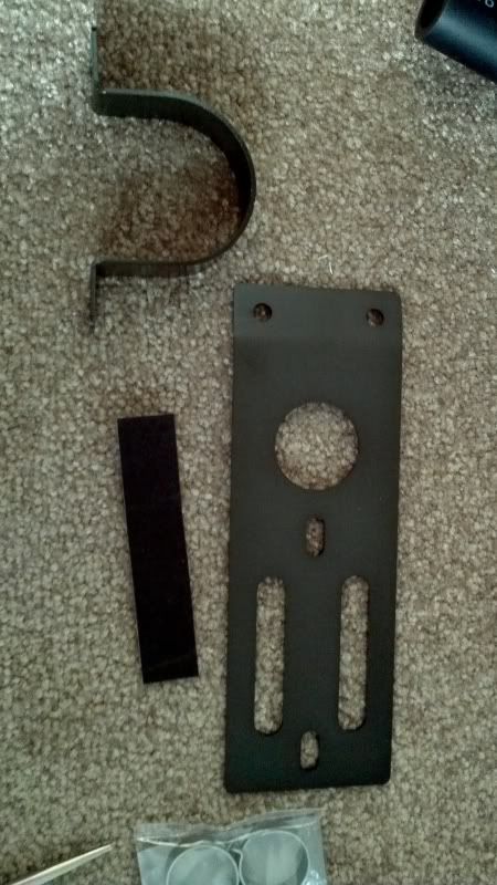
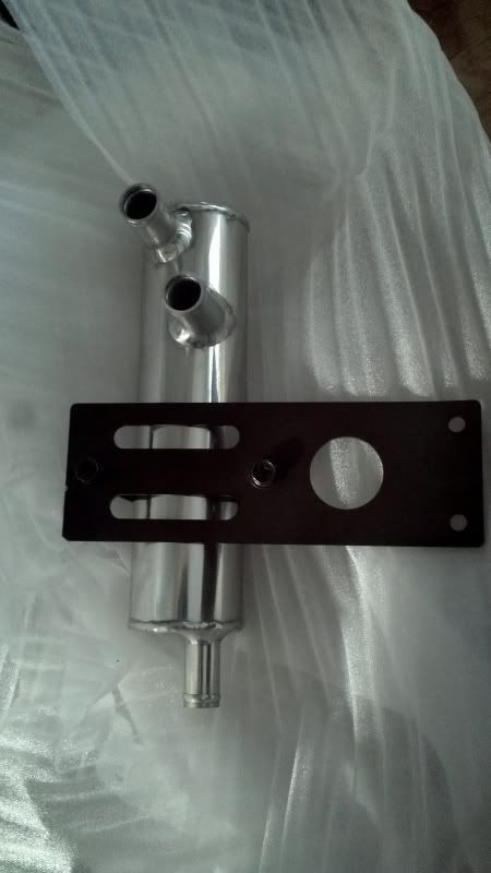
The clamp can be left slightly loose to aid in final orientation of the can.
Next, the oil drain line can be installed on the rear turbo oil drain fitting.
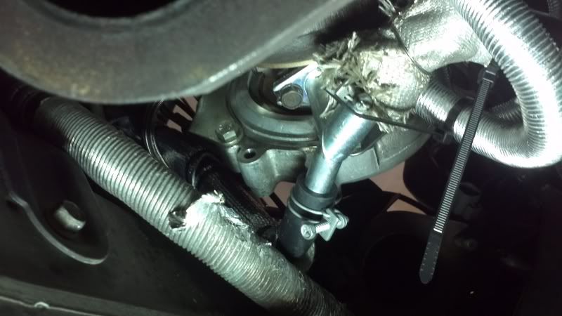
With this complete, the can may be bolted on to the car in its final resting place, which is the power steering reservoir bracket.
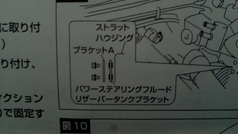
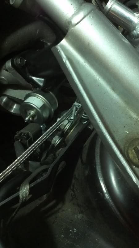
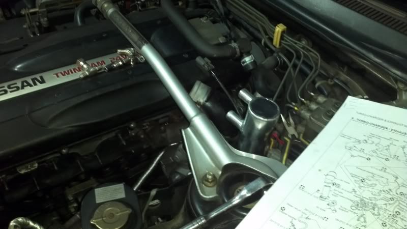
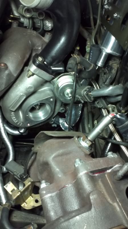
The oil drain line can be attached to the can.
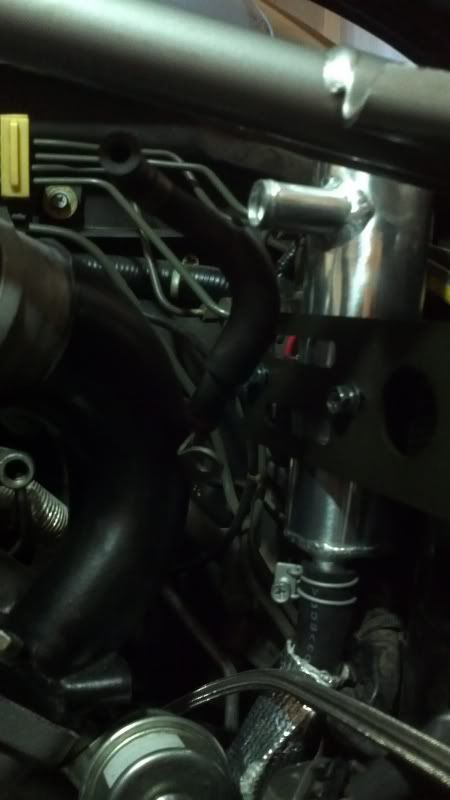
The original fitting that the recirculation hose to the rear turbo suction connected to needs to blocked with the included parts.
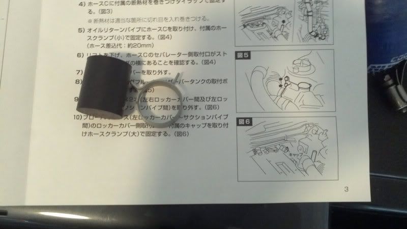
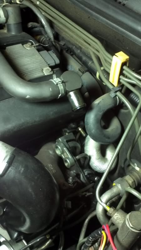
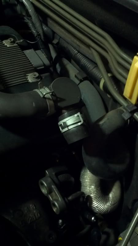
Next, the hose connecting the two fittings on valve covers, needs to be cut into for the tee that will connect to the separator. I marked the rough location of the tee before taking the hose off.
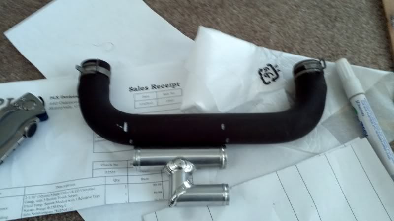
The instructions say 20mm should be cut but its more like 30mm due to the size of the solder or braze or whatever holds the tee together. Everything is then fixed together with the included fittings.
Finally, all the hoses can be installed. The top fitting on the separator connects to the rear compressor suction pipe. The middle fitting connects to the tee on the cam covers. This is where the can needs to be turned slightly so as to not flex the hoses, after which it can be firmly secured with the clamp.
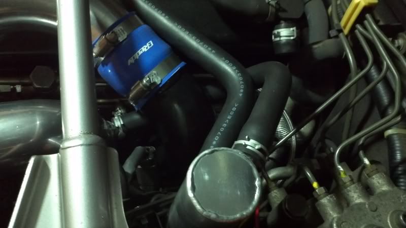
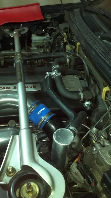
Comment
-
Eek! expensive air/oil can!!
Nice though it's time to get that on the road!!! I'm probably not going to be bringing my car on the road this year (yay another year!!!) but I have something nice to show this time and not a pulsar Black 1991 GTR. Serious garage stand mantle/parts car.
Black 1990 Pulsar GTiR. Sold
Silver 1989 GTR. Sold
Black 2010 Subaru WRX. Weekend warrior. Sold.
Black 2013 F-150 FX4 ecoboost. Daily driver.
White 2012 Ford Explorer Limited. Family wagon.
Sorry for my offensive comments, I r socially retard.
lolstart by having A ROLLING GTR then we talk u ******* mofo funzy little *****
Comment


Comment