Announcement

Collapse
No announcement yet.

Work Log: R33 GT-R

Collapse
X
 
  • Filter
  • Time
  • Show
Clear All
new posts

  • P/S Reservoir Relocate Part 2

    Originally posted by nimblestix View Post
    So much effing sex!!!! Cant wait to see this completed, when the time comes post a video of her breathing!
    This will has big fap potential.

    Good work buddy.
    Thanks! I will take a video of her breathing hopefully with soemthing better than a crappy phone cam. She hasn't breathed properly for 2 years now!

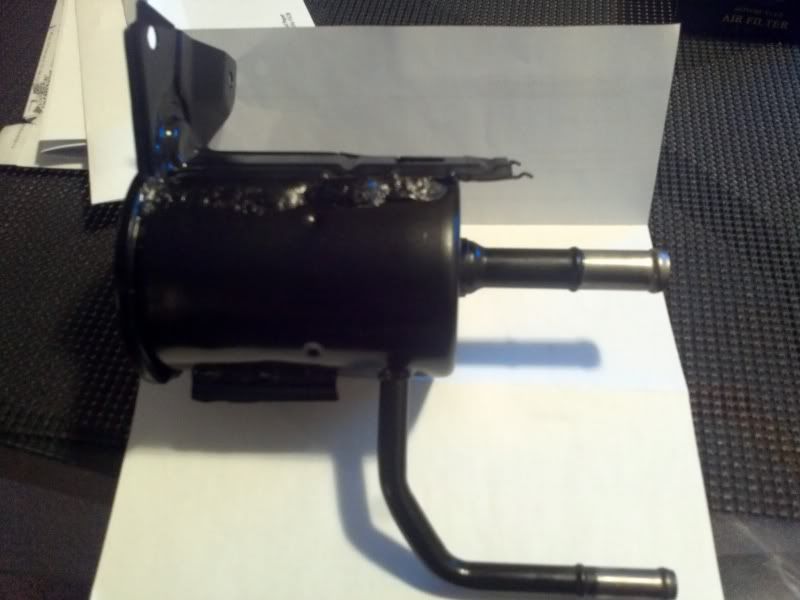
    Continuing on to something I left a while back, the power steering reservoir relocate to the rad support. I had already cut off most of the stock bracket that holds the reservoir to the strut tower.

    I joined the rad support to the reservoir with some shoddy looking welds
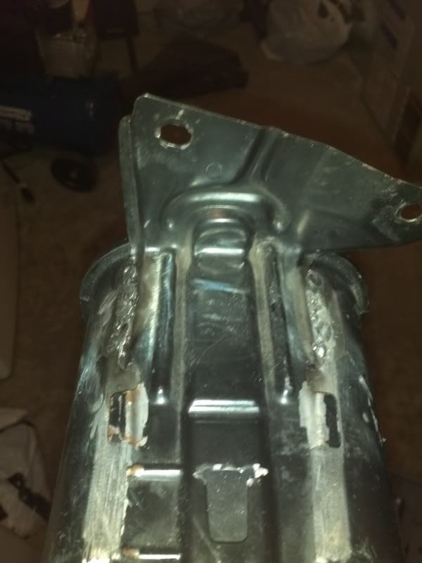


    But it fit well at least.
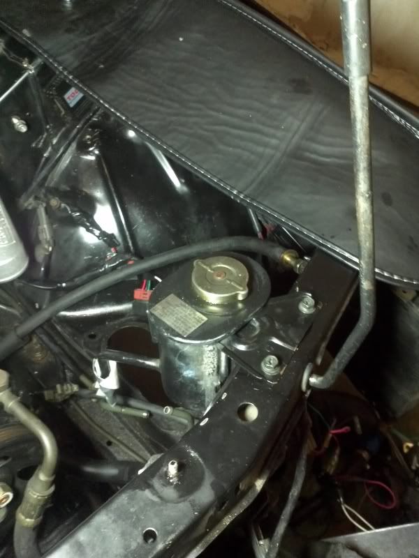


    I then had the reservoir blasted over the holidays..so much P/S fluid kept coming out, the guy had to bake out the remaining fluid.


    I decided that my welds didnt pass QC, so I hastily covered it up with some epoxy putty.
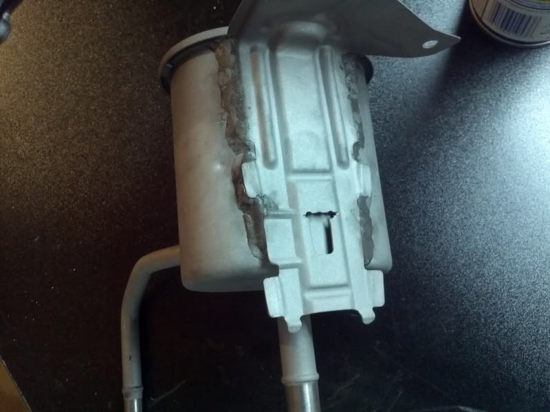


    The cap had lost its brass-looking coating so it looked like the rest of the reservoir. Rather than painting it, I opted to polish it.
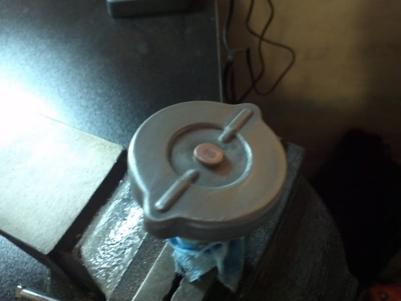


    I worked my way up from 100 grit to 1500 grit sandpaper in stages.

    I then applied the rubbing compound prior to polishing.
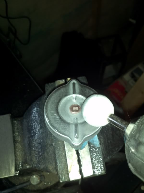


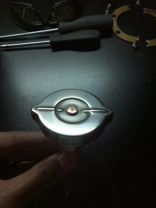
    After two step polishing compound for steel and Fluidfilm..obviously it can look a lot better with more time but I didn't want to spend so much time and have it start surface rusting right away..I will employ the time honored wait and see approach before spending more time on it.


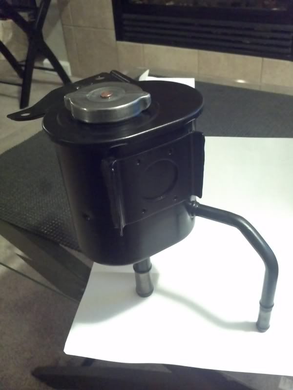
    I washed the reservoir and cleaned it thoroughly inside and out in preparation for painting. I painted the reservoir with VHT black caliper paint, and later baked it in the oven for curing.
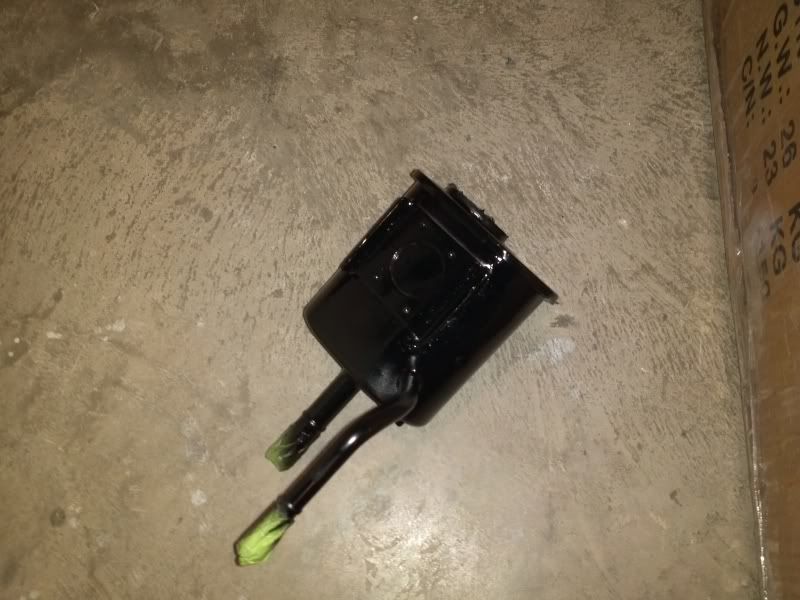


    And the final product..


    Comment


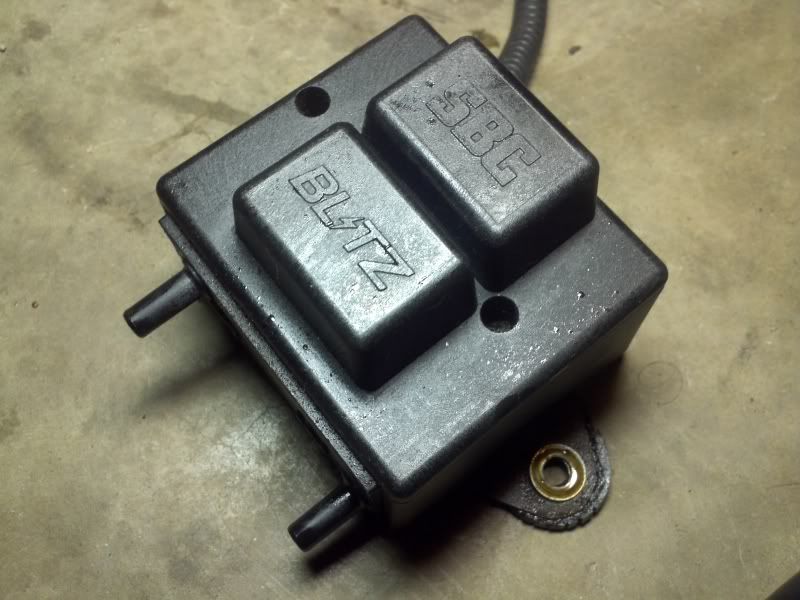
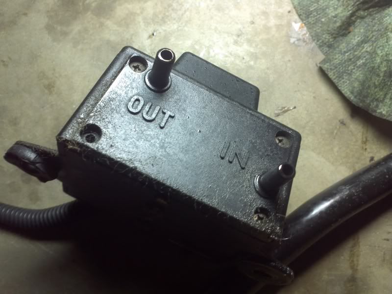
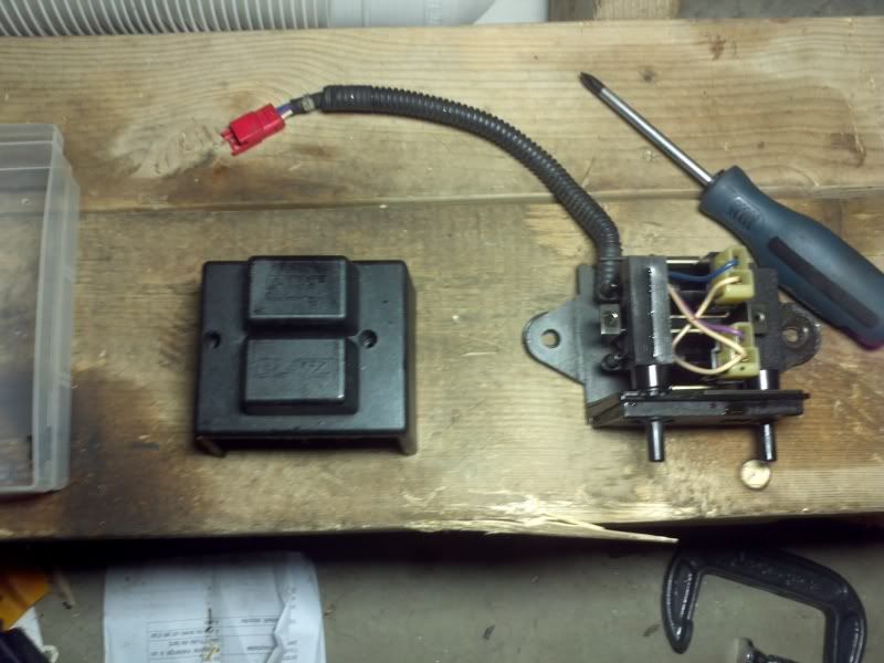
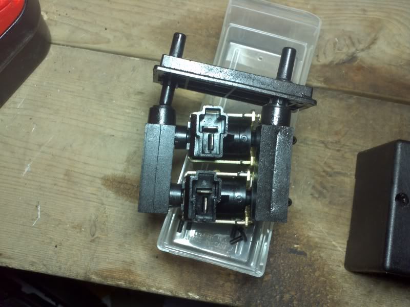
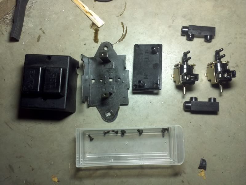
    • Since there was copious amount of oil in the intake piping, I felt the boost controller needed a cleaning. I disassembled it fully and sprayed it inside and out with electrical contact cleaner.


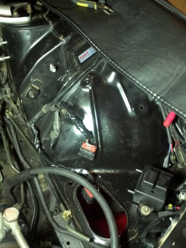
      After reassembling it, I rerouted the loom for it to reach around the engine bay so I could mount the boost controller close to the turbo. I used one of the stock intake mounting holes.

      Comment


      • Turbo Oil Drain

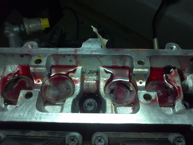
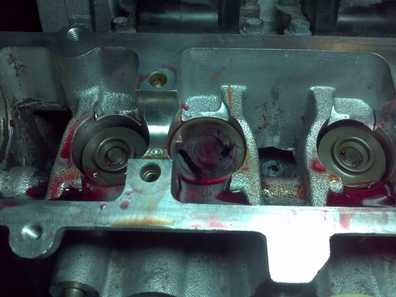
        All this while I have been tackling the cams. I went too far and bent a couple of valves due to being stupid and leaving two pistons at TDC while checking valve clearances. Rather than attempt (and probably botch) a valve job, I will be sending the head off to a rebuilder (either the old head or new head) for a valve job and fitting and shimming the Poncams.


        And life goes on..in a dejected mood I started on the turbo oil drain.

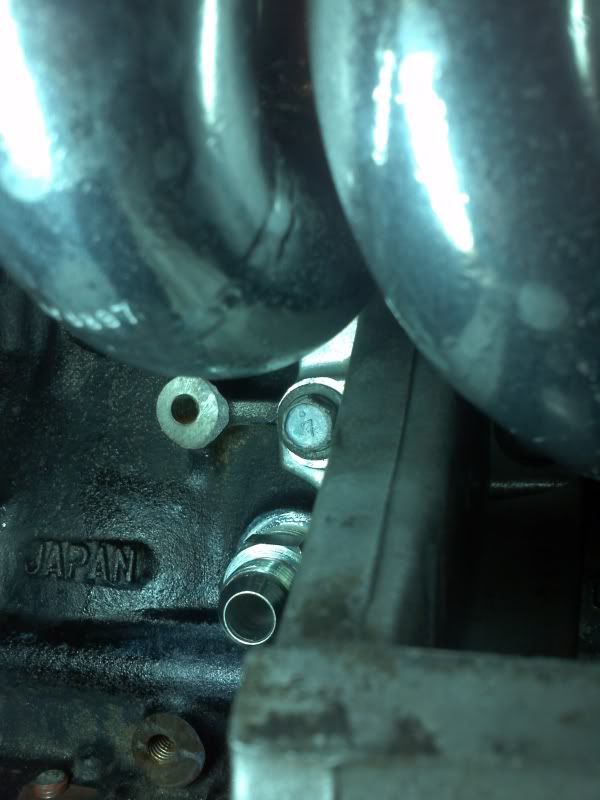
        There is a lot of conflicting information on the the thread size of the front turbo oil drain hole on the block. 3/4" NPT, 3/4" BSP, etc. But in actual fact, the hole is 3/4" BSPT!

        Some people get away with using NPT in this hole. Most of the pipe threads on the RB26 are BSPT. Excerpt from website below:

        It may fit, but the thread forms are different. NPT/NPS and BSP threads are not compatible due to the differences in their thread forms, and not just the fact that most diametrical sizes have a different pitch. NPT/NPS threads have a 60° included angle and have flattened peaks and valleys (this is a Sellers thread form); BSP threads have a 55° included angle and have rounded peaks and valleys (this is a Whitworth thread form).
        http://pipeandhose.com/node/2

        A BSPP fitting will not work in a BSPT hole at all. This is because the threads are parallel as opposed to tapered. This is analogous to our NPT and NPS on this side of the world.

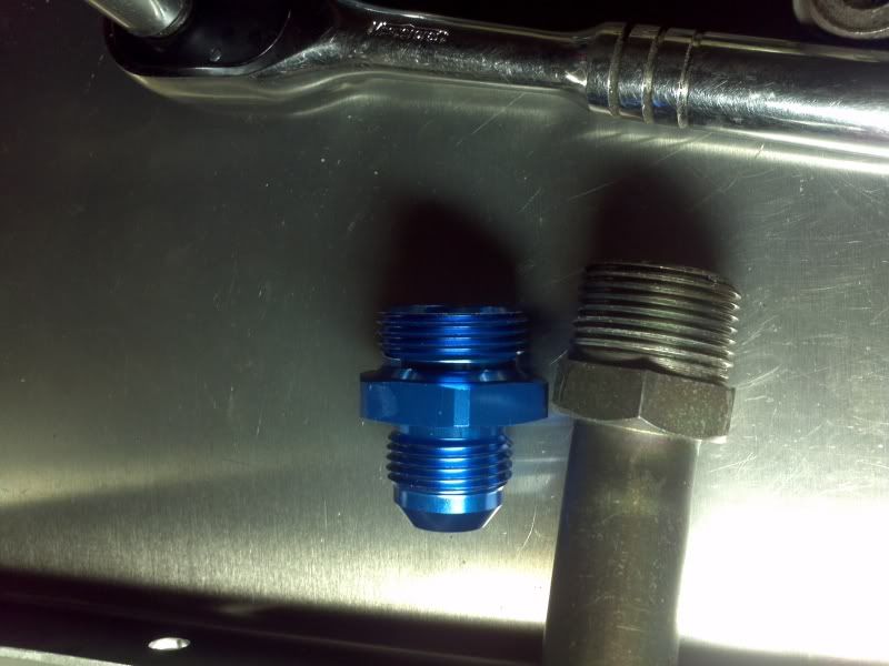
        I couldn't find a BSPT x AN fitting anywhere in this size ( I actually didnt know the hole was BSPT initially). Here's a picture showing the difference between the BSPP x AN fitting I had purchased initially and the stock fitting.


        Now, with no BSPT x AN fittings availalable for this size, what to do? Go with a NPT fitting? No way, more research required.

        An industrial equivalent for the AN fitting exists; this is the 37 degree JIC fitting. Here is an excerpt from Wiki on this:

        JIC fittings, defined by the SAE J514 and MIL-F-18866 standards, are a type of flare fitting machined with a 37-degree flare seating surface. JIC (Joint Industry Council) fittings are widely used in fuel delivery and fluid power applications, especially where extremely high pressure is involved. The SAE J514 standard replaces the MS16142 military specification, although some tooling is still listed under MS16142. JIC fittings are dimensionally identical to AN (Army-Navy) fittings, but are produced to less exacting tolerances and are generally less costly.
        From other research, the general consensus was these fittings could be used interchangeably in low pressure, non-critical applications. Problem solved. And you will see shortly on how well these fittings fit together!

        Here is some more reading on AN vs JIC fittings:

        http://www.mechanicsupport.com/articleStronger.html

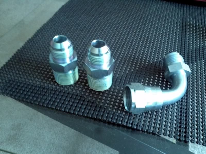
        Ok, so I picked up some 5/8" Male JIC x 3/4" Male BSPT adapters made from plated steel along with a 90° Tube Elbow, 5/8" JIC Male x 5/8" JIC Female Swivel just in case I needed such an elbow. I got them from www.discounthydraulichose.com. The fittings are sized by hose size similar to -AN (-10 AN being 5/8" hose size).


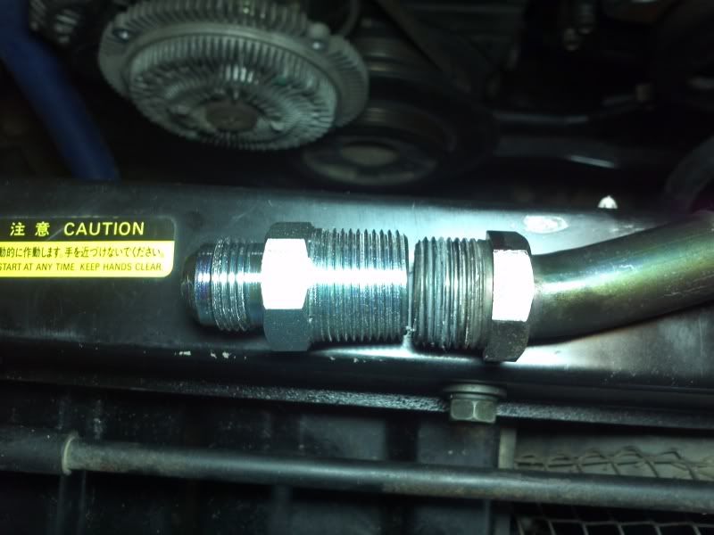
        The stock fitting and the JIC x BSPT adapter side by side:


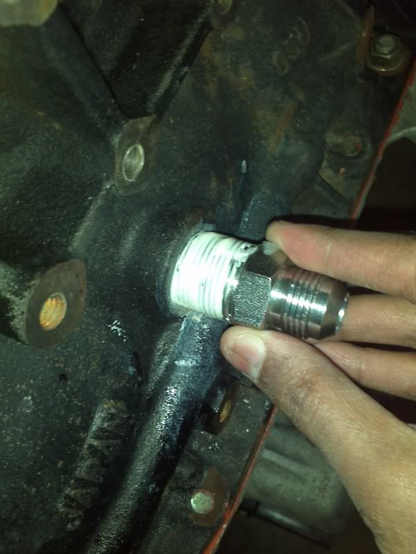
        The adapter threads in normally with thread sealant till it bottoms out.


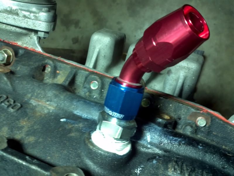
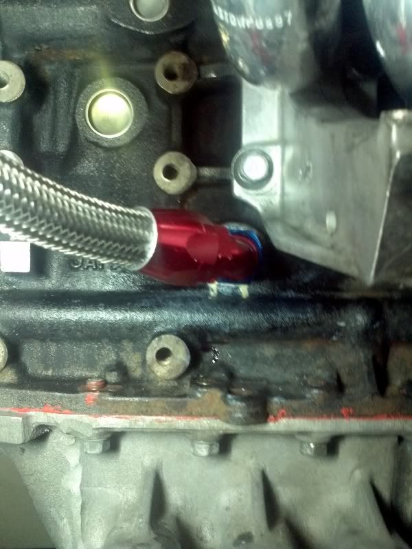
        Here is the -10 AN 45 elbow fitted onto the JIC adapter.


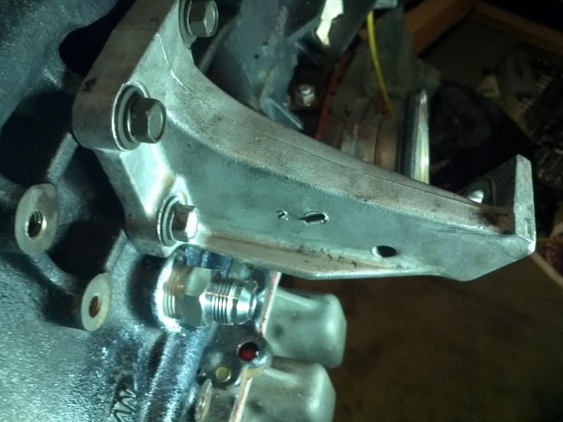
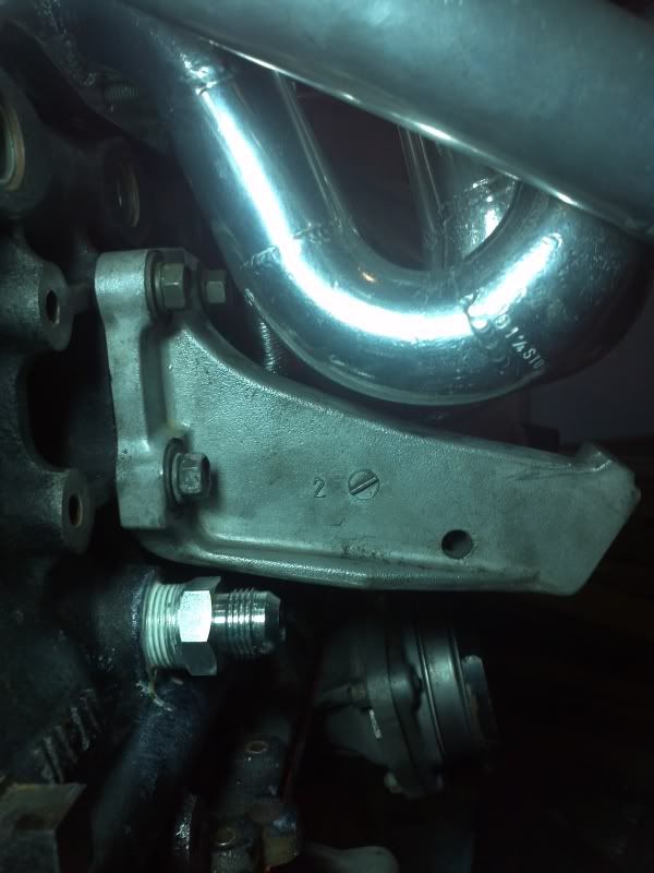
        For fit up purposes, I installed the motor mount bracket. Not a whole lot of room between the manifold and bracket!


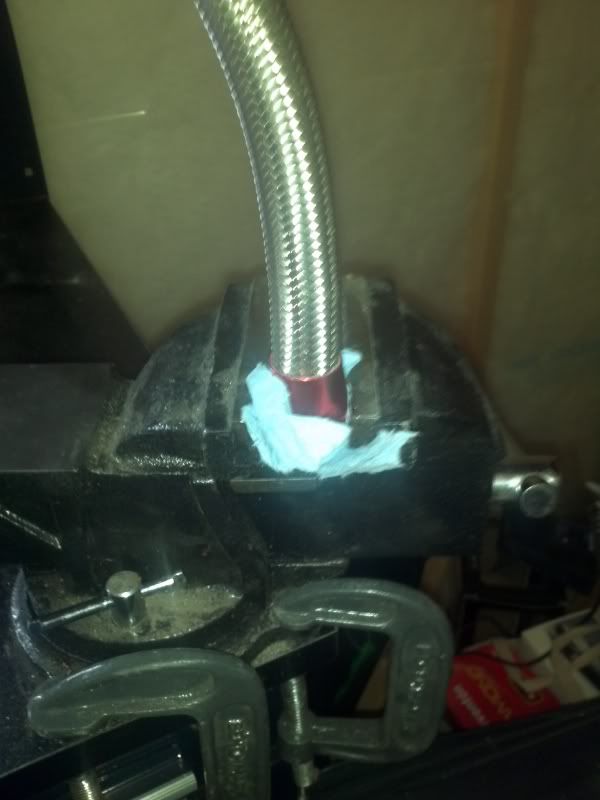
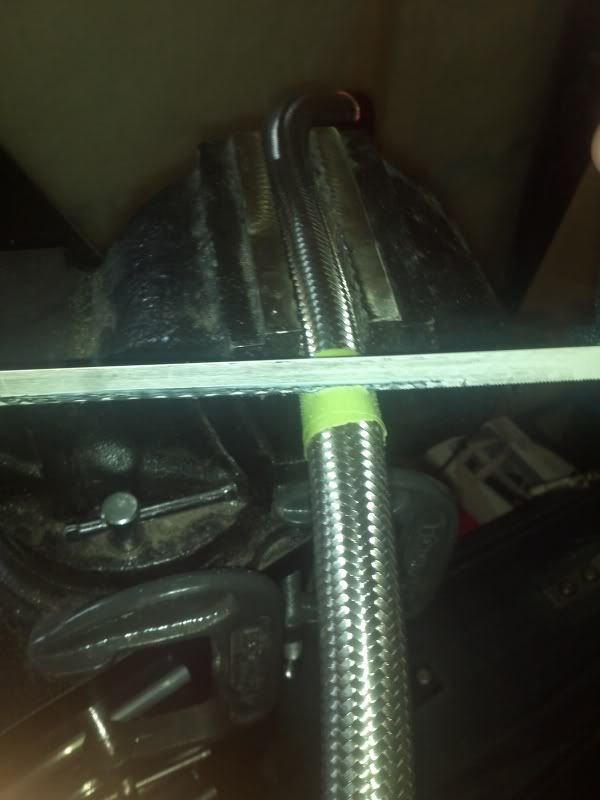
        I then started on making the hose, following typical instructions. I wanted to fit the elbow onto the full length hose before cutting it. First, the hose end is prepped by trimming off any loose braiding and strands. Then, the hose is twisted and pushed into the mating fitting up to the bottom of the threads, then backed out 1/16".


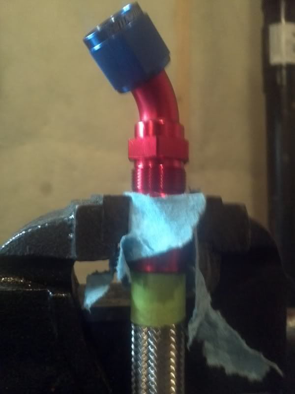
        Then, the difficult part, after lubing everything up nicely, the nipple/adapter portion is threaded into the hose end, with the chamfered portion of the nipple expanding the hose against the hose end fitting and forming a tight seal. I did strip the first section of thread the first time, but after some frantic cleaning and brute force, it was in there good. If the hose backs out of the hose end, you have to start over; fortuantely, it didn't.


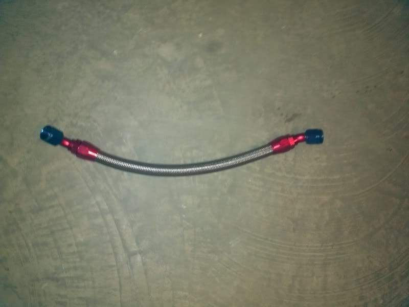
        I took the full hose w/ AN fitting at the end and installed it on the turbo to get a good cutting location. To cut the hose, the location needs to be taped up to prevent the braids from fraying too much. Any excees fraying can be trimmed with a Dremel.


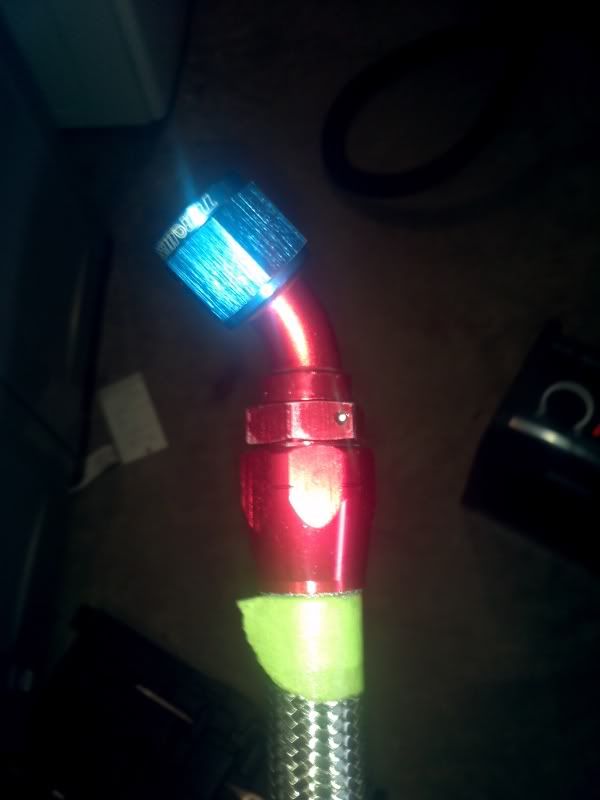
        Followed the same procedure, and voila.


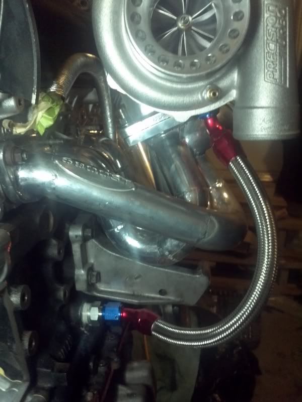
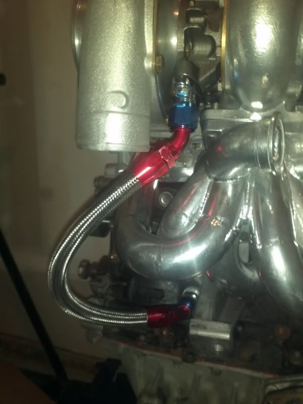
        The hose installed. I chose this route as this clears the manifold sufficiently and I don't have my A/C compressor in the way anymore.


        I am able turn the 45 swivel fitting on the block more to get more slope on the line. This does cause some loading on the hose, but it is crucial to have a downward slope over the whole line to aid proper oil draining.
        Last edited by PurpleStreak; 02-05-2013, 05:07 PM.

        Comment


        • Good news, I now have a proper camera with good low light capability so hopefully this will spell the end of crappy pics. In the mean time, I'm using my new Z10 for pics.

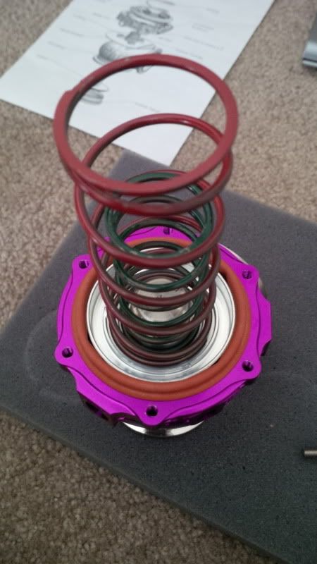
          I installed the springs in the wastegates. Since I don't know if I would be trailering the car down at this point, I spec'd my springs to run the car on wastegate pressure only, for 10 psi. This would still maintain the rule of thumb boost pressure (2x the wastegate spring pressure) for my planned 20ish psi which an EBC could handle. Ideally I would like to run a spring rate of 15 psi which would be the minimum boost the car would see.

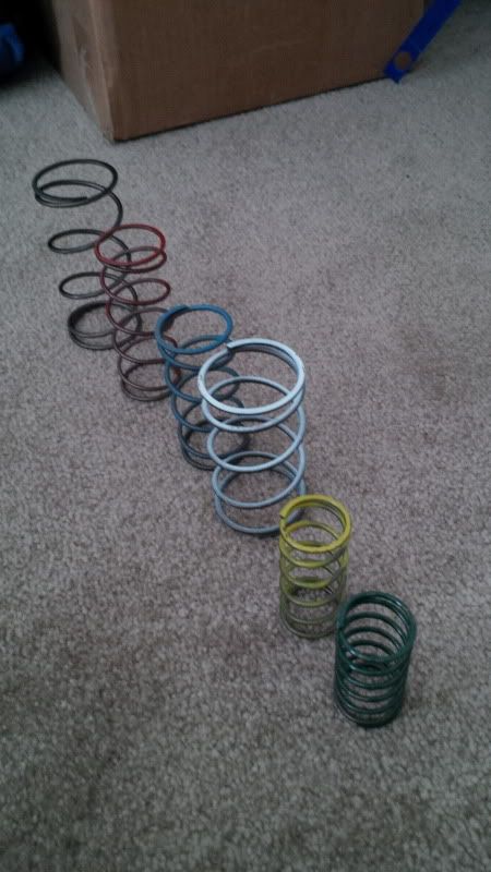
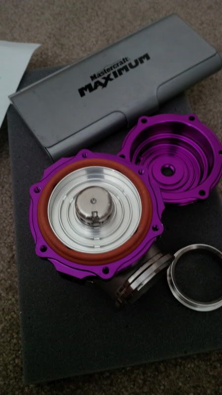
          The wastegates came with all the available springs.


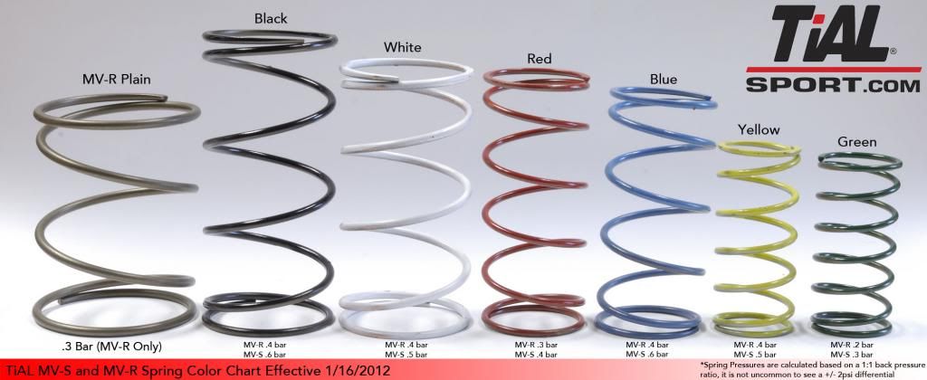
          Here are the spring rates by color


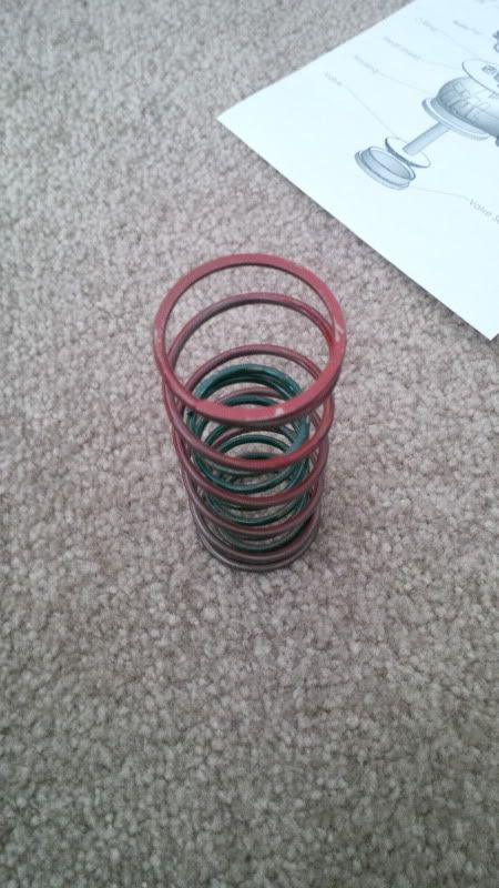
          Thus I picked the red and green spring to give me a combined 0.7 bar, which is roughly 10 psi.


          I opened up the wastegates and installed the springs. Maybe I'll use a C-clamp next time so I don't end up wrestling with it and wasting time.


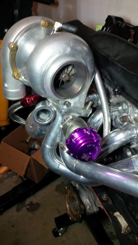
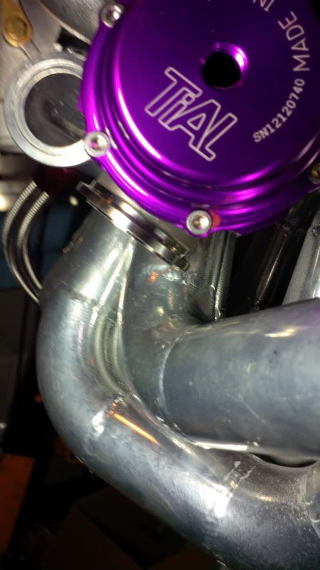
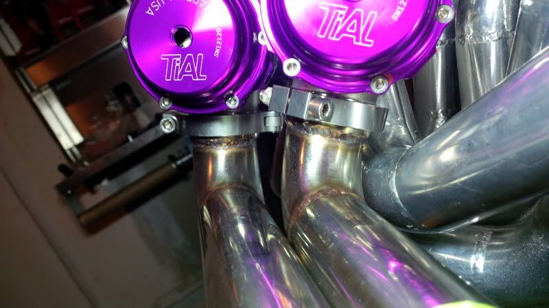
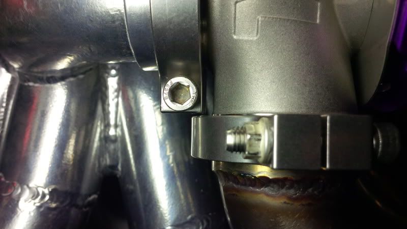
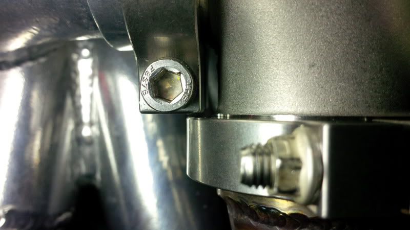
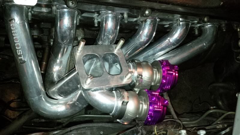
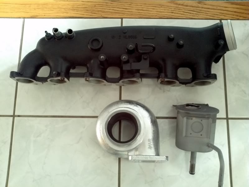
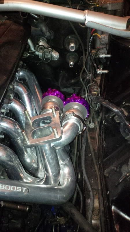
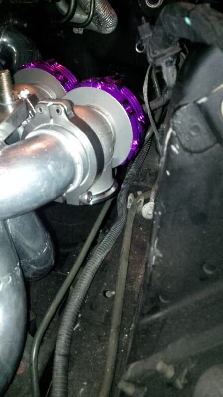
          Next I installed the wastegates on the manifold. It is a tight fit, especially on the outboard wastegate, where the clamp can only be installed one way. I then installed the dump tubes to get an idea of routing.


          Look at the clearance between the two clamps! If the inlet clamp is not installed with the bolt centerline on the horizontal, then there is interference with the outlet clamp.


          I then tried test fitting the entire assembly into the engine bay. It would not fit with the dump tubes in place. However, without the dump tubes on, there is plenty of room once the manifold is elbowed in there.


          Also got the head off (good luck finding cheap 12 point sockets for the ARP head nuts in Fort Mac).


          Block is clean, has been WD40'd and covered up for now


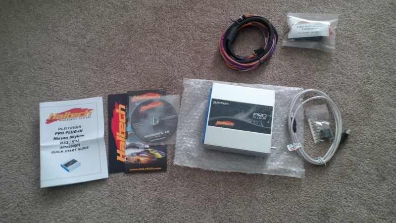
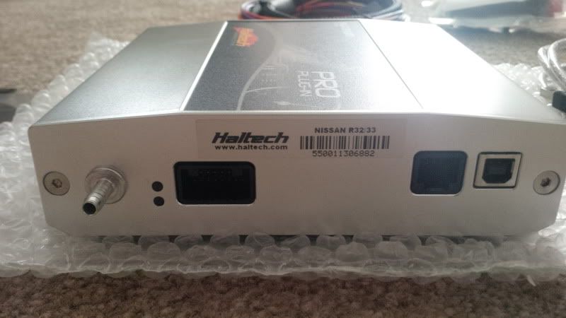
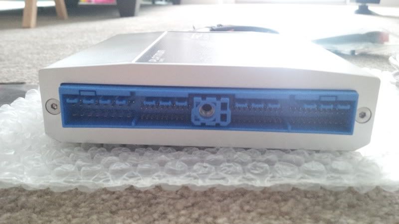
          Also got my new badboy ECU, along with an aux harness and 3 bar MAP sensor...looks like more Molex connector fun


          Comment


          • curious

            whats the advantage to going with 2 wastegates at 38mm versus say a 50-52mm gate?

            yes i know 38+38 will flow better but with the setup up you got are you really worried about boost creep?

            just curious
            Currently rollin' in a 1997 Nissan 240sx こうき


            The artist formally known as Cory Scheuer

            Comment


            • Originally posted by h4X6 View Post
              curious

              whats the advantage to going with 2 wastegates at 38mm versus say a 50-52mm gate?

              yes i know 38+38 will flow better but with the setup up you got are you really worried about boost creep?

              just curious
              The two wastegates are only there to maintain the twin pulse effect; having runners to one wastegate on a twin pulse manifold would defeat the purpose (IMO).

              As far as wastegate sizing is concerned, Kyle recommended going with a 60mm wastegate if going with an undivided manifold; he gave the reason that the older style wastegate using a single smaller wastegate do not flow as well, and that a small wastegate on his manifold would not yeild adequate boost control.

              Maybe boost creep would be an issue with a 50-52 mm gate, because the turbo is on the larger side and the boost levels are not that high, which would mean more exhaust flow would have to be diverted to maintain the desired boost ( larger wastegate ). If the turbo was made to run at its maximum flow point, you could get away with a smaller wastegate as the flow through the wastegate wouldnt be that high.

              Here are the full rules of thumb about wastegate sizing

              Wastegate sizing is inversely proportionate to the desired level of boost and is somewhat independent of the size or power of the engine. One vendor's guide for wastegate sizing is as follows:[3]

              big turbo/low boost = bigger wastegate
              big turbo/high boost = smaller wastegate
              small turbo/low boost = bigger wastegate
              small turbo/high boost = smaller wastegate

              Comment


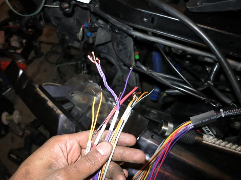
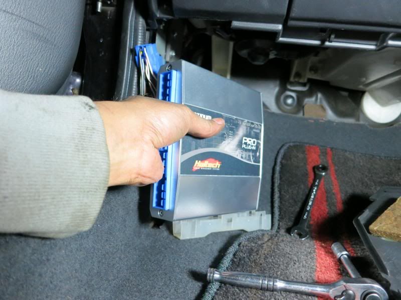
              • Here is bit of an update..I've done a few things and left it half finished for the most part. Here is the minimal electronics scope for this upgrade, which is to install the new Haltech Plug in ECU and run the aux harness and connect the 3 Bar MAP sensor, the wideband sensor and run a DSO to the A-LSD (future).

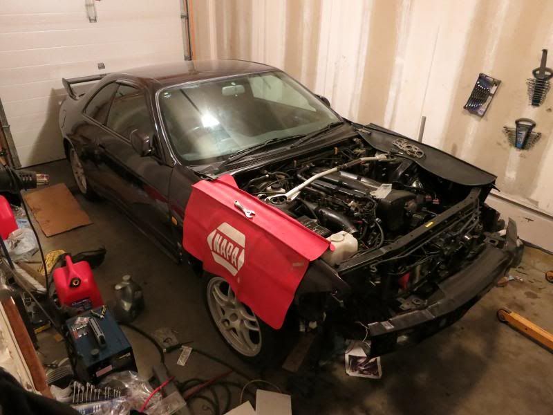
                Also picked up a better camera. The car as it sits.


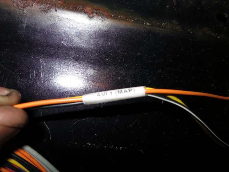
                The aux harness has all the wires convieniently labelled.


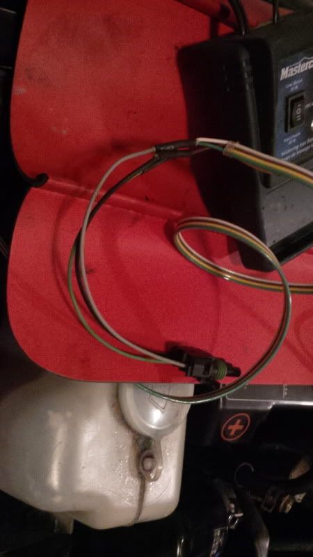
                I didn't want to deal with Molex pins so I just picked up a piggy for a GM 3 bar MAP sensor and we soldered it to the wires we would be running into the cabin.


                Each pin is marked and only fits on the sensor one way

                Pin A= GROUND

                Pin B= MAP SIGNAL OUTPUT

                Pin C= 5V

                We also utilized 2 and 3 wire quick connects at the ends of the harness and at the gauge/sensor ends. Might replace these with proper PC connectors I have ordered down the road to prevent signal degradation through these massive connectors.


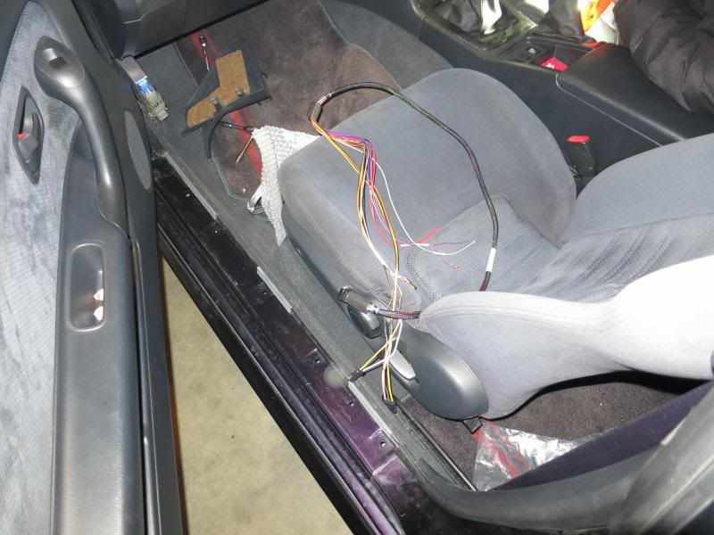
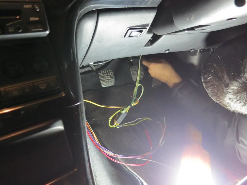
                The harness has been run and the wires are tucked away.


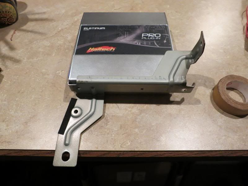
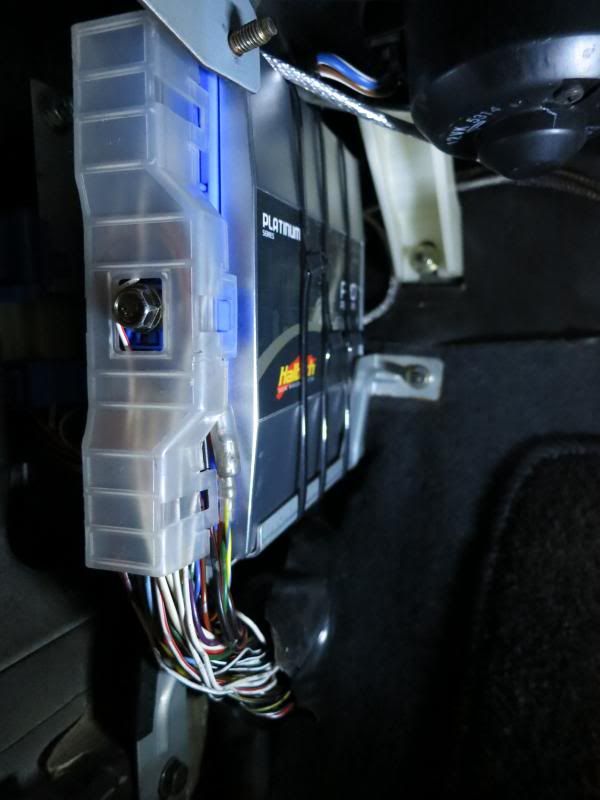
                As for the ECU itself, there are no mounting tabs on the unit itself.


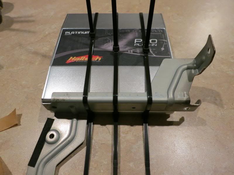
                The stock R33 GTR has a bolt on bracket which can be used.


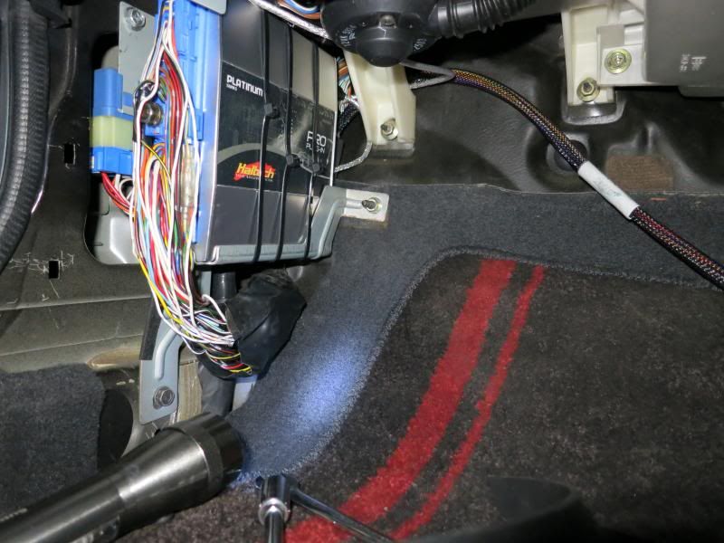
                Three zip ties and some double sided tape later..


                The rest is straight forward. Ran the USB cable into the glove box for easy access.


                Last edited by PurpleStreak; 03-22-2013, 12:29 PM.

                Comment


                • Sick sick sick!!! Getting excited to see it run! Are you tuning in Calgary John? When do you figure going?
                  Black 1991 GTR. Serious garage stand mantle/parts car.
                  Black 1990 Pulsar GTiR. Sold
                  Silver 1989 GTR. Sold
                  Black 2010 Subaru WRX. Weekend warrior. Sold.
                  Black 2013 F-150 FX4 ecoboost. Daily driver.
                  White 2012 Ford Explorer Limited. Family wagon.

                  Sorry for my offensive comments, I r socially retard.

                  start by having A ROLLING GTR then we talk u ******* mofo funzy little *****
                  lol

                  Comment


                  • Hey Frank, I'm excited to see it run properly too! I will probably be taking it in sometime in spring, depending on how Fort Mac weather is (garage is too small to pull an engine so have to do it on the driveway); I'll keep you updated!

                    Comment


                    • very nice

                      Comment


                      • Oil Pan Baffle Install

                        Since the car will be experiencing many high G-force manoueveres turning off Highway 63 onto Confed, I am installing a Tomei oil pan baffle to alleviate any oil starvation issues.

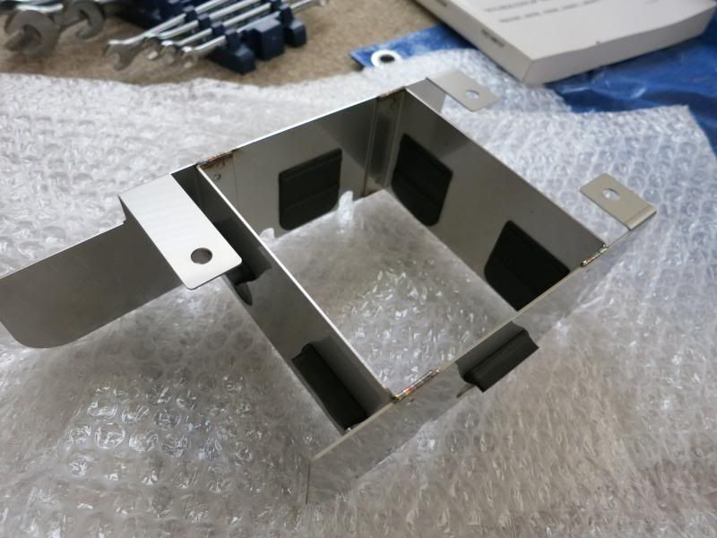
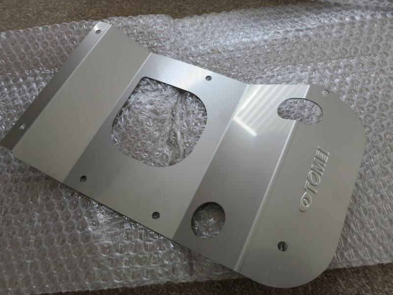
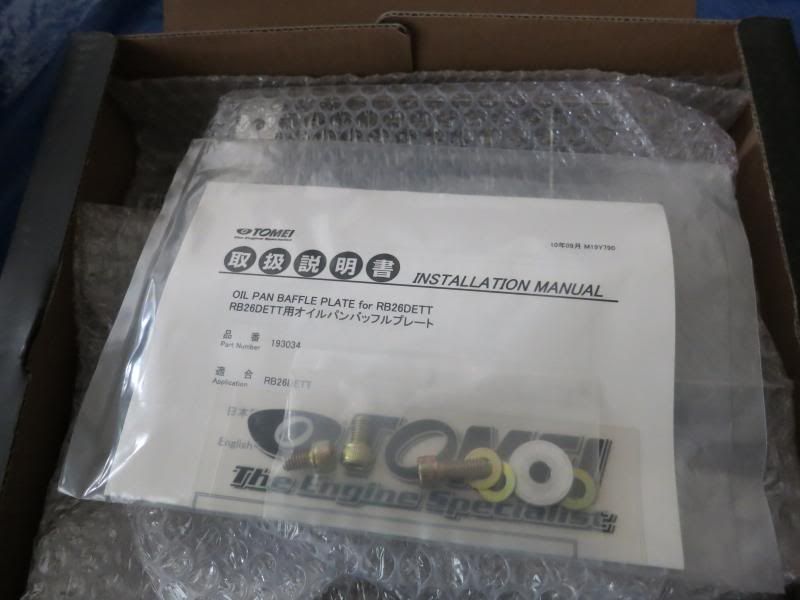
                        Here are the bottom and top pieces of the baffle. The kit also comes with 3 bolts, washers and a spacer, and Engrish instructions!


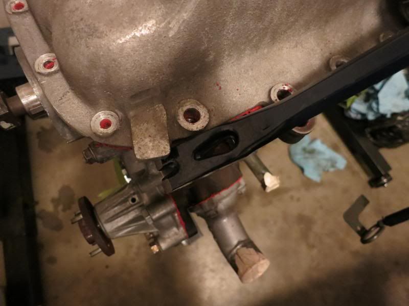
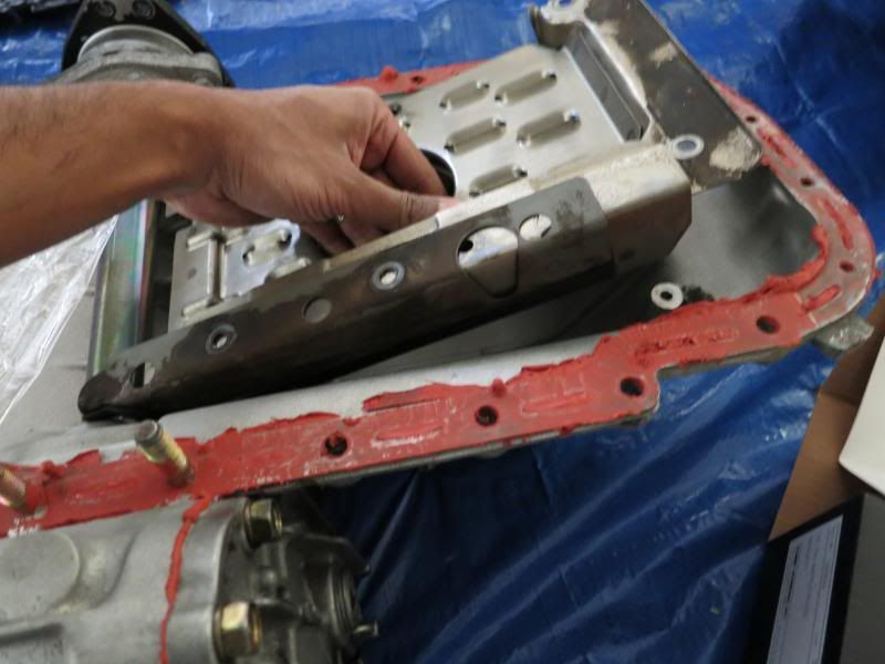
                        FIrst I removed all thh bolts for the oil pan and levered it off the block.


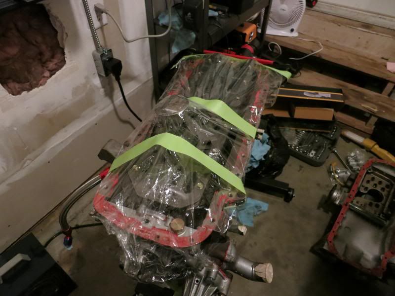
                        I ghetto wrapped the bottom of the block and then moved the pan to a warmer location and started removing the stock baffle.


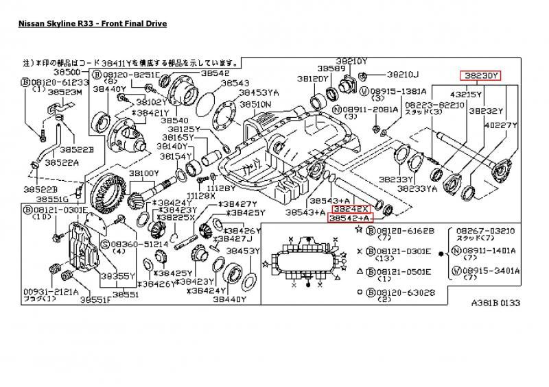
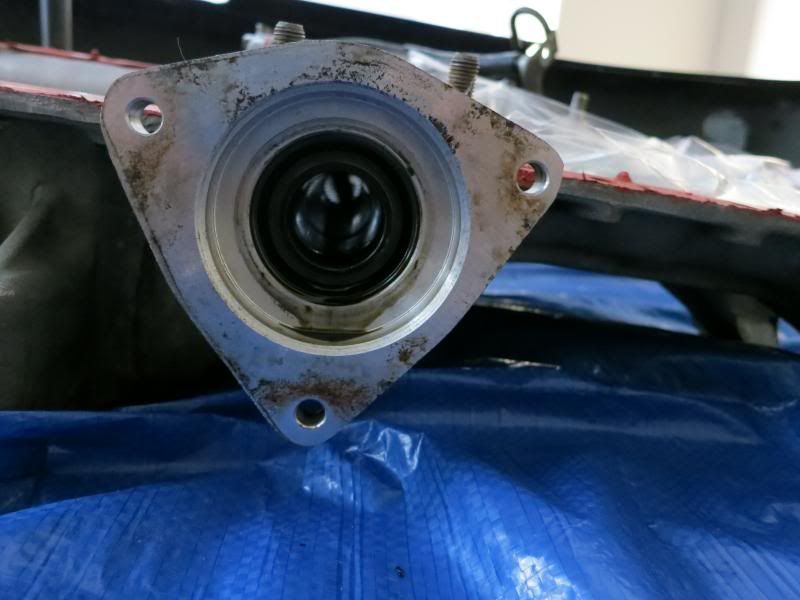
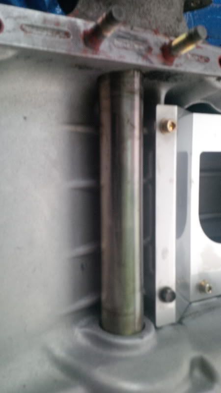
                        As part of the install, the oil return holes have to be enlarged. In order to this, the tube that the driveshaft passes through (38242X) has to be removed. This means unbolting the driveshaft (3823DY) from the passenger side of the oil pan and pulling it out.


                        To do this the oil seal that retains the tube (38542+A) has to be removed, and it is destroyed during removal. After this , the tube slides out with some fiddling.


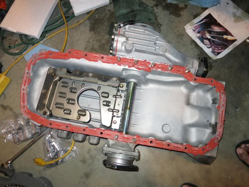
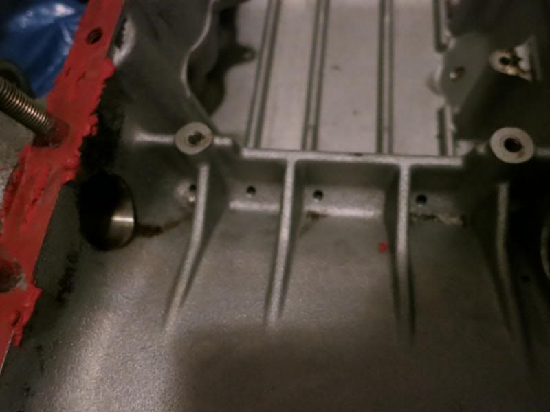
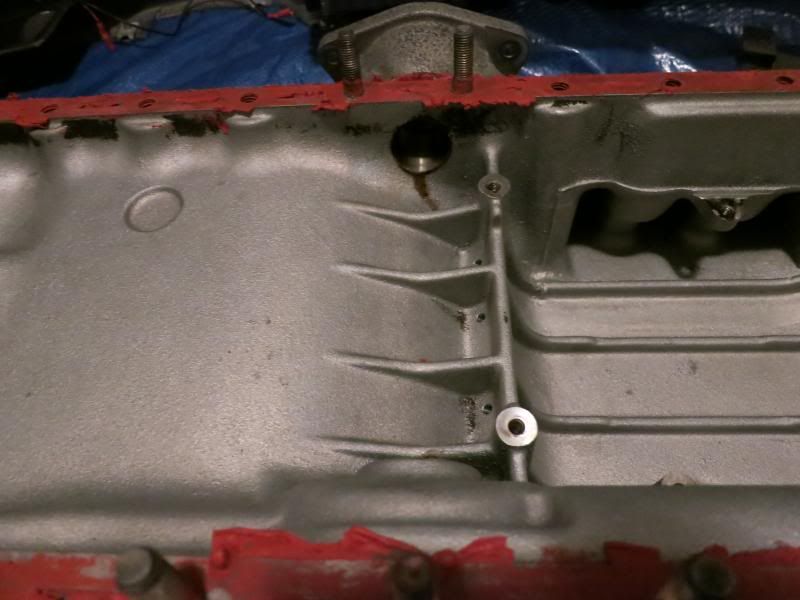
                        Here are the oil return holes that need to be modified.


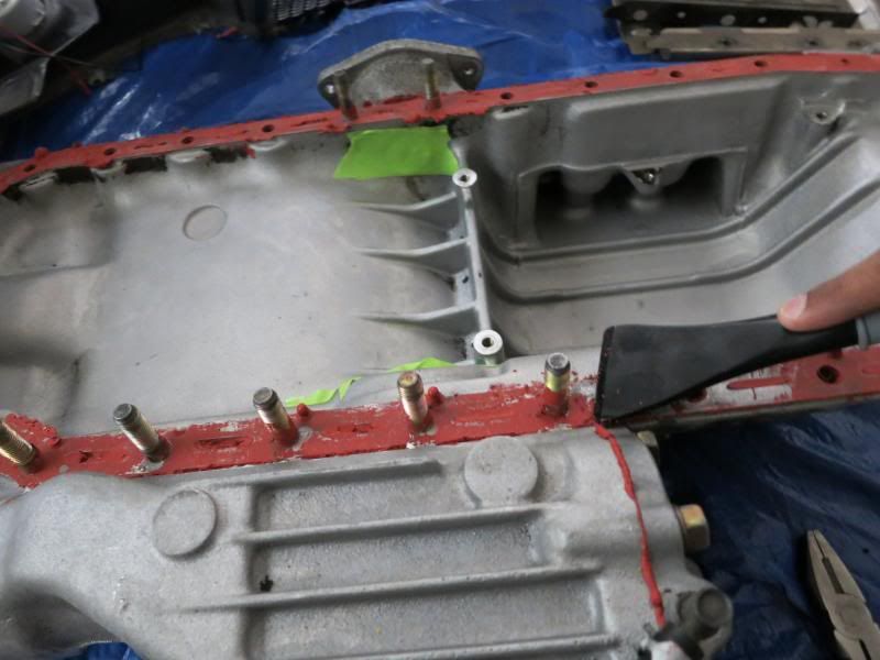
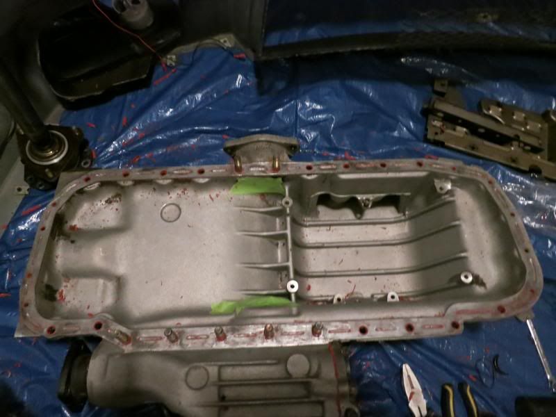
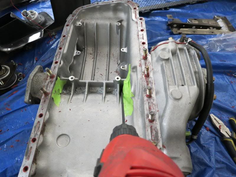
                        Before doing anything, I taped up the open orifices in the pan and scraped of the remaining gasket maker with my SKRAPR HD PRO.


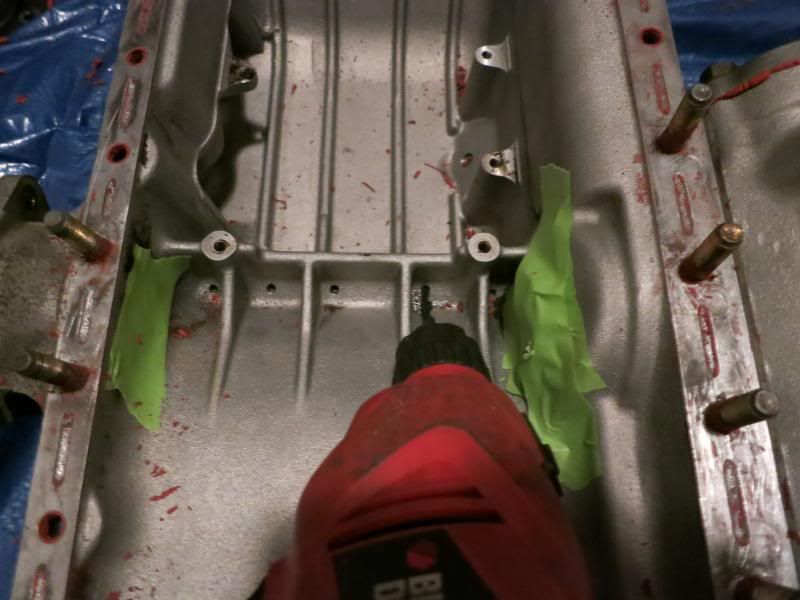
                        I then drilled out the oil return holes with the closest imperial equivalent of 5mm. I had to use an aircraft extension bit for the hole closest to the diff.


                        I then cleaned up the enlarged holes with a file, and vacuumed off all the shavings and gasket maker. I picked off any remianing shavings with some cleaner and lint free rags.

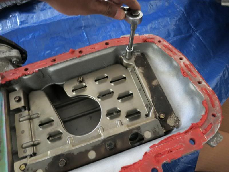
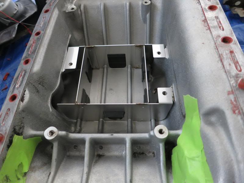
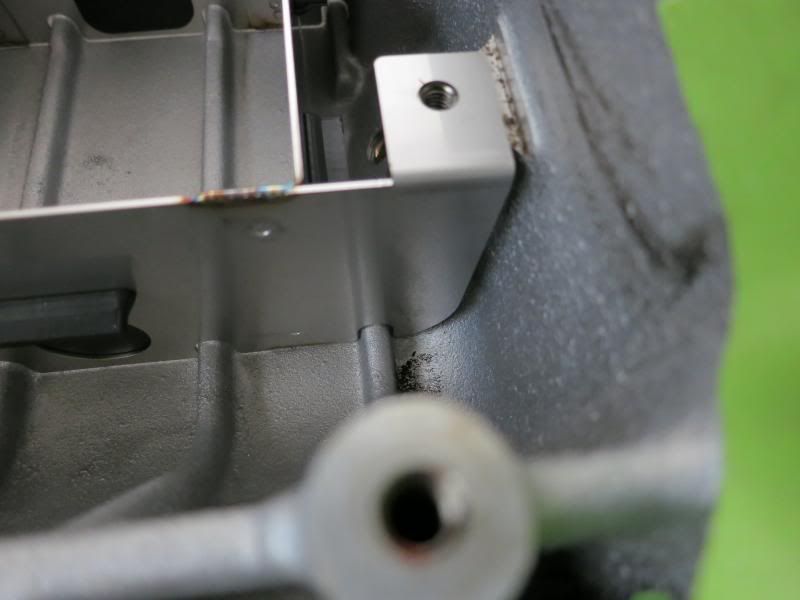
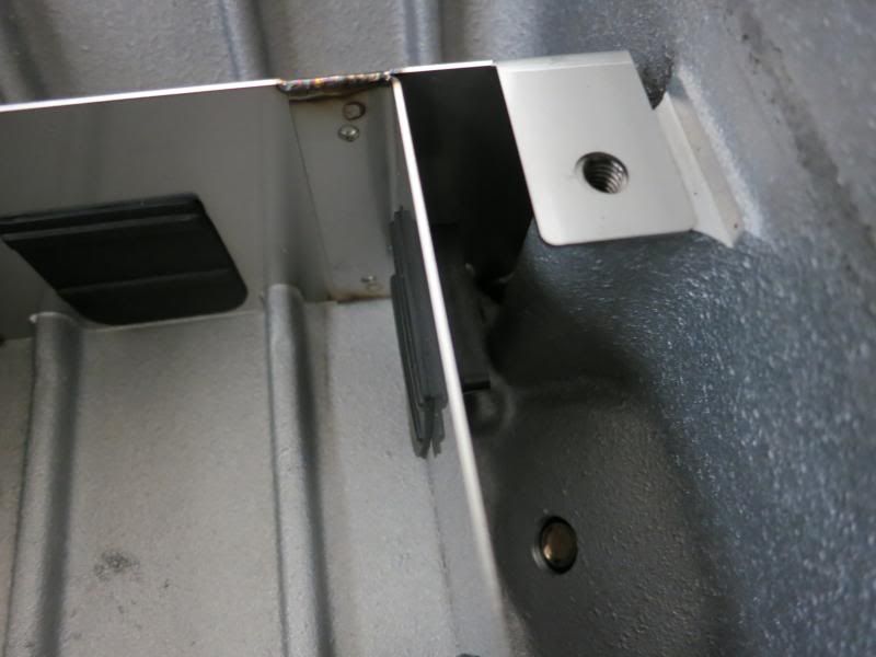
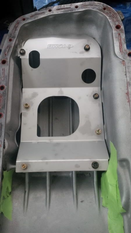
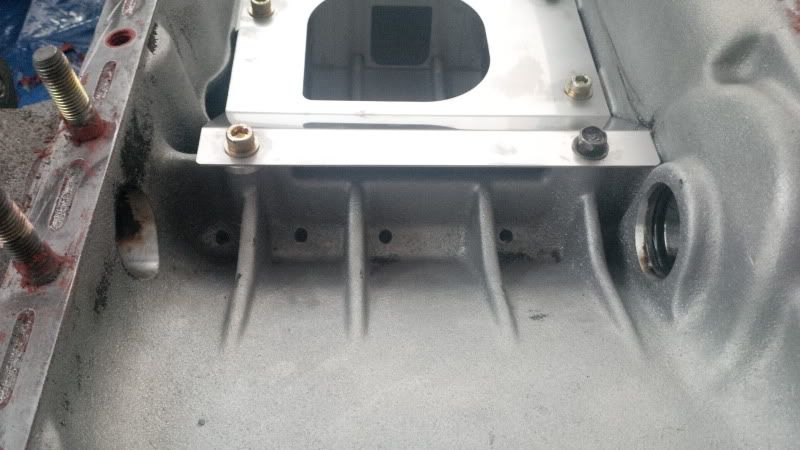
                        With the holes enlarged and the pan relatively clean, I test fit the baffle. When fitting, the clearance between the baffle and the ribs on the bottom of the pan have to be checked. The bolts are only to ensure that the baffle sits in its final location.


                        No interference to be seen. Nice bit of kit!


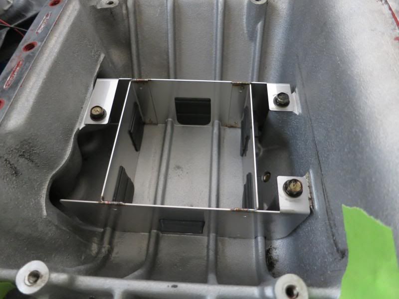
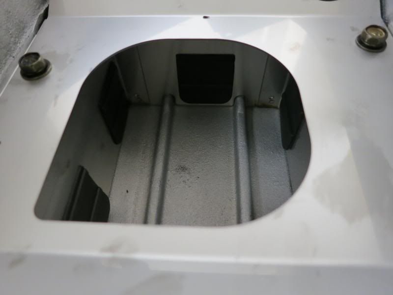
                        I then installed the bolts and spacer in their final location, utilizing only the shortest stock bolts. I torqued everything to ~6.25 lb.ft.


                        I then put the driveshaft tube back in its place. Just need to drift the driveshaft seal into place and the oil pan is ready for reinstallation!

                        Comment


                        • Cool install write up, better than the manual. As for the gaskets, I recommend replacing the front diff seals too (pinion and shafts), mine leaked and had wait till the next engine pull.
                          Black 1991 GTR. Serious garage stand mantle/parts car.
                          Black 1990 Pulsar GTiR. Sold
                          Silver 1989 GTR. Sold
                          Black 2010 Subaru WRX. Weekend warrior. Sold.
                          Black 2013 F-150 FX4 ecoboost. Daily driver.
                          White 2012 Ford Explorer Limited. Family wagon.

                          Sorry for my offensive comments, I r socially retard.

                          start by having A ROLLING GTR then we talk u ******* mofo funzy little *****
                          lol

                          Comment


                          • Originally posted by NismoS-tune View Post
                            Cool install write up, better than the manual. As for the gaskets, I recommend replacing the front diff seals too (pinion and shafts), mine leaked and had wait till the next engine pull.
                            Thank you, specifically which seals are you referring to? ( if you can reference the part #s on the FAST picture I posted ) Thanks in advance!

                            Comment


                            • I'll try to remember which. I have et to confirm if they were a match as ive been lazy on the parts car and spending all m time with the wife and kid...

                              Edit:
                              Front pinion seal
                              *Nissan 38189-03V00 or C8189-03V00.
                              Front diff cover seal? RTV
                              Front Inner Drive Shaft Oil Seal - Nissan Skyline GTR (driver)
                              38342-03V01.
                              Front Inner Drive Shaft Oil Seal - Nissan Skyline GTR (passenger)
                              38342-03V11.
                              Black 1991 GTR. Serious garage stand mantle/parts car.
                              Black 1990 Pulsar GTiR. Sold
                              Silver 1989 GTR. Sold
                              Black 2010 Subaru WRX. Weekend warrior. Sold.
                              Black 2013 F-150 FX4 ecoboost. Daily driver.
                              White 2012 Ford Explorer Limited. Family wagon.

                              Sorry for my offensive comments, I r socially retard.

                              start by having A ROLLING GTR then we talk u ******* mofo funzy little *****
                              lol

                              Comment


                              • Well that's odd, the part numbers are slightly different for the R33. I hope they are compatible; this is a BNR32 engine, I ordered only the passenger side oil seal in anticipation of this job. I'll order the other two as well, thanks!

                                Comment

                                Working...
                                X